En
gl
is
h (
G
B)
18
10.1 Conex
®
DIS-G terminal assignment
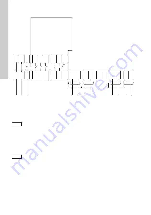
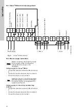
Fig. 6
Conex
®
DIS-G terminal
10.2 Power supply connection
Voltage supply for Conex
®
DIS-G:
•
Connect the protective conductor (PE) to terminal
6.
•
Connect the neutral conductor (N) to terminal 4.
•
Connect the phase (L) to terminal 2.
Voltage supply for electrically isolated relay
contacts:
•
Connect the protective conductor (PE) to terminal
5.
•
Connect the neutral conductor (N) to terminal 3.
•
Connect the phase (L) to terminal 1.
TM
03
7
044
45
06
2
4
6
1
3
5
8
10 12
14 16
7
9
11
13 15 17
20 21
23 24
18 19
26 27
29 30
L
N PE
+
-
+
-
+
-
-
+
Power supply
> 1000 m
> 100 m
For supply
o
f the f
loat
ing
cont
act
s
Limit 1 /
sensor
1 (M
1)
Lim
it
2
/ sensor 1 (M1)
Lim
it
1
/ sensor 2 (M2)
Lim
it
2
/ sensor 2 (M2)
Ala
rm relay
Cu
rrent
ou
tput se
nsor 1 (M1
)
Sensor 1
Sensor 2
C
u
rrent output sensor 2
(M2)
Caution
Before connecting, check that the values
for the supply voltage
and frequency
correspond to the values on the
nameplate.
Note
Switch the device on and off by switching
the power supply on and off accordingly.
The device itself is not equipped with a
separate on/off switch.
Summary of Contents for Conex DIS-G
Page 2: ...2 ...
Page 345: ...345 ...


