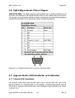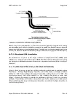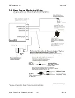
GRT Avionics, Inc.
May 2019
Sport EX/Horizon EX Install. Manual
36
Rev. A
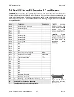
A-4: Sport EX/Horizon EX Connector A Pinout Diagram
CAB-EXA-01:
Connector A is a female 25-position D-sub connector that attaches to the
display unit’s male 25-position D-sub connector. Wires for Primary Power IN and Ground
are pre-installed in the connector housing. Commonly used optional wires are supplied
as loose, terminated wires. Wire colors assigned to serial ports are suggestions only.
NC
denotes “No Connection.”
Connector A harn
ess is 4’ long; longer harnesses are
available by special order.
*NOTE:
Optional Serial
Ports 4-6 are enabled
with
the
VFR/IFR
Package or added with
the Serial Option.
**NOTE:
OAT
and
Magnetometer
connections
apply
to
Sport
EX
ONLY
.
Connections are
NC
for
Horizon EX.
Figure A-5: 25 Position
Female D-sub Connector
(Insertion View)
.
Pin
Function
Wire Color
A1
Serial 6 OUT
*
WHT/BLK
A2
Serial 1 OUT
WHT/GRN
A3
Serial 5 OUT
*
ORG
A4
Serial 2 OUT
BRN
A5
Serial 4 OUT
*
YEL/WHT
A6
NC
A7
NC
A8
RS-485 A (Trig TT22 A)
A9
RS-485 B (Trig TT22 B)
A10
Outside Air Temp Input
**
GRY
A11
Magnetometer Power OUT
**
BLU
A12
Magnetometer Ground OUT
**
WHT/BLU
A13
Magnetometer Serial Input
**
ORG/BLK
A14
Primary Power IN
RED
A15
Secondary Power IN
RED/BLU
A16
NC
A17
Ground
BLK
A18
NC
A19
Serial 2 IN
YEL
A20
Serial 1 IN
WHT
A21
Serial 4 IN
*
GRN/BLK
A22
Serial 5 IN
*
YEL/BLU
A23
Serial 3 IN
GRY/RED
A24
Serial 6 IN
*
YEL/GRY
A25
Serial 3 OUT
GRY/BLK
Installed in connector housing.
Supplied as loose, terminated wire.


