


GRT Avionics, Inc.
May 2019
Sport EX/Horizon EX Install. Manual
24
Rev. A
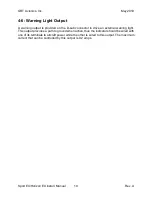
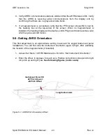
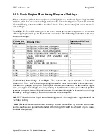
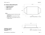
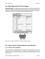
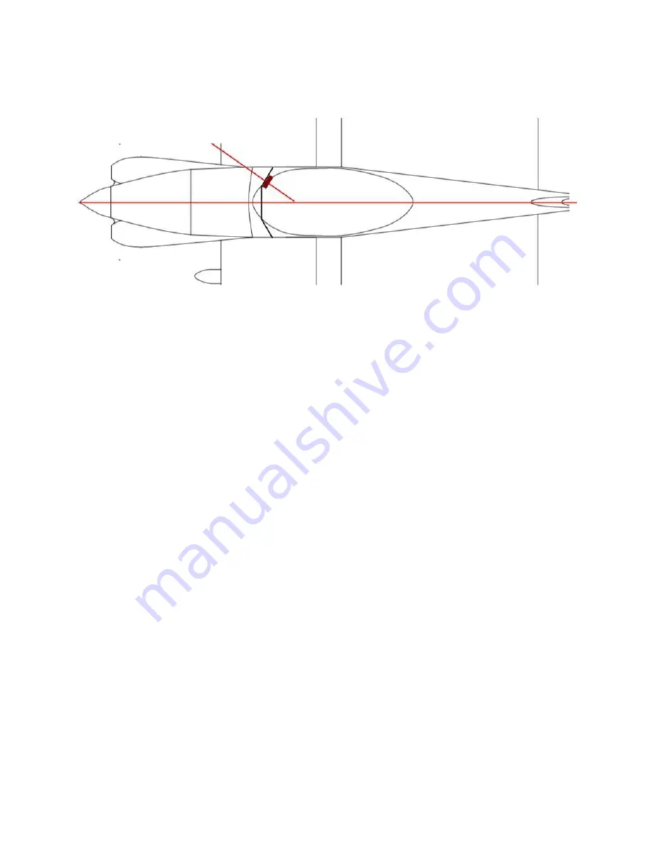
Display Unit Tilted Toward Pilot
15° Right Yaw =
+15 Yaw Offset
Longitudinal Axis
Figure 5-2: AHRS Yaw Orientation Offset
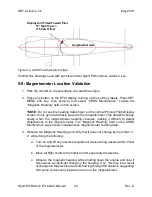
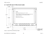
Panther
line drawings used with permission from Sport Performance Aviation, LLC.
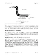
5-9: Magnetometer Location Validation
1. Park the aircraft on a level surface and start the engine.
2. Press any button on the EFIS display to bring up the soft key labels. Press SET
MENU soft key, then scroll to and select
“AHRS Maintenance.” Locate the
“Magnetic Heading” field on this screen.
*NOTE:
Do not use the heading data shown on the normal Primary Flight Display
screen; this is gyro data that is slaved to the magnetometer. This data will change
slowly when the magnetometer heading changes, making it difficult to detect
disturbances to the magnetometer.
The “Magnetic Heading” field on the AHRS
Maintenance page shows instantaneous magnetometer heading data.
3. Observe the Magnetic Heading and verify that it does not change by more than +/-
2° while doing the following:
a. Turn on and off any electrical equipment whose wiring passes within 2 feet
of the magnetometer.
b. Move all flight controls from limit to limit, especially the ailerons.
c. Observe the magnetic heading while shutting down the engine and note if
this causes a significant change in the heading. If so, this may be a result
of changes in the electrical currents flowing through the airplane, suggesting
that some current-carrying wires are too to the magnetometer.


