


Installation
WARNING
INSTALLATION OF THE BRAISING PAN
MUST BE DONE BY A CERTIFIED
ELECTRICIAN OR GROEN AUTHORIZED
REPRESENTATIVE QUALIFIED TO WORK
WITH ELECTRICITY. IMPROPER
INSTALLATION CAN RESULT IN INJURY TO
PERSONNEL AN/OR DAMAGE TO
EQUIPMENT.
Internal wiring for the Braising Pan is supplied
complete. When you receive the unit, it is ready for
connection. A wiring diagram is located inside the
control box on the right side of the pan, as well as in
this manual (pp. 28-33).
Your pan was performance-tested at the factory to
confirm that all controls and heating elements were
functioning correctly.
Installation is as follows:
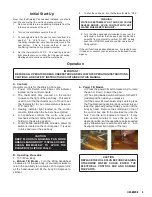
1. Set the unit in place and level it by turning the
adjustable feet. Crank the pan body to a
completely horizontal position. Check levelness
by placing a spirit level on the bottom of the pan.
The unit must be level to avoid uneven cooking
across the pan.
2. Make a
waterproof
connection with the incoming
power line at the electrical service entrance at the
bottom of the connection box at rear of control
console. A BX connection is
NOT
recommended.
ELECTRICALLY GROUND THE UNIT
at the
proper terminal.
3. Provide the proper electrical supply as specified
on the electrical information plate. Comply with
local codes and the National Electrical Code
ANSI/NFPA 7- latest edition.
4. Use only copper wire, rated at least 75ºC and of
proper gage. See chart on page 8.
5. Standard equipment is shipped ready for 208V,
240V, or 480V, 3-phase operation. Refer to the
wiring diagram located on the inside cover of the
control box and the instructions below for
conversion to single-phase operation.
A jumper wire and “conversion” label are included
with the unit. They can be found in a plastic bag
attached to the trunnion assembly inside the
control box.
CAUTION
BEFORE ANY ELECTRICAL CONVERSION,
VERIFY THAT THE BRANCH CIRCUIT
WIRING IS ADEQUATE TO HANDLE ANY
INCREASE IN AMPERAGE REQUIREMENTS.
R E F E R T O T H E E L E C T R I C A L
SPECIFICATIONS LISTED BELOW.
6.
For conversion from 3-phase to 1-phase
i. Verify that the branch circuit wiring is adequate
for any increased amperage requirements. (See
table on next page)
ii. 1-phase requires two jumper wires. One
jumper wire exists on the terminal block for 3-
phase input. The second jumper wire is located in
a plastic bag inside the control box.
iii. Attach jumper wires to terminal block as per
wiring diagram for 1 phase supply.
iv. Complete “conversion label” (supplied in bag)
and adhere it to the control box near the UL
dataplate.
OM-BMP-E 7
Summary of Contents for Eclipse BPM-30E
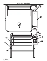
Page 18: ...18 OM BMP E PARTS LIST BPM BPP E 8 9 17 1 2 3 5 13 18 20 21 ...
Page 19: ...OM BMP E 19 PARTS LIST BPM BPP E 4 6 7 10 11 12 19 22 23 14 15 16 ...
Page 24: ...24 OM BMP E WIRING DIAGRAM BPM 30E ...
Page 25: ...OM BMP E 25 WIRING DIAGRAM BPP 30E ...
Page 26: ...26 OM BMP E WIRING DIAGRAM BPM 40E ...
Page 27: ...OM BMP E 27 WIRING DIAGRAM BPP 40E ...
Page 30: ...30 OM BMP E ...
Page 31: ...OM BMP E 31 ...
Page 32: ...32 OM BMP E ...
Page 33: ...NOTES OM BMP E 33 ...
Page 34: ...NOTES 34 OM BMP E ...
Page 35: ...NOTES OM BMP E 35 ...


