


COPYRIGHT © 1995 BY GRIZZLY INDUSTRIAL, INC. REVISED MAY, 2019 (BL)
WARNING: NO PORTION OF THIS MANUAL MAY BE REPRODUCED IN ANY SHAPE
OR FORM WITHOUT THE WRITTEN APPROVAL OF GRIZZLY INDUSTRIAL, INC.
#JB11261 PRINTED IN TAIWAN
V3.05.19
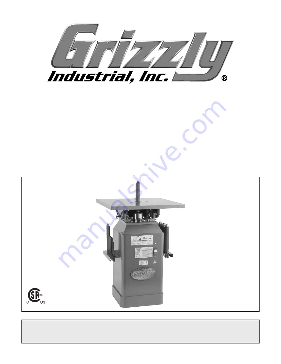
MODEL G1071
1 HP OSCILLATING SPINDLE
SANDER
OWNER'S MANUAL
(For models manufactured since 11/10)
177335
Summary of Contents for G1071
Page 40: ......


