background image

-30-

Model G0852 (Mfd. Since 12/18)

System Grounding

Since plastic hose is abundant, relatively inexpen-
sive,  easily  assembled  and  air  tight,  it  is  a  very 
popular  material  for  conveying  dust  from  wood-
working machines to the dust collector. 

We  recommend  only  using  short  lengths  of  flex-
ible hose (flex-hose) to connect the woodworking 
machine  to  the  dust  collector.  However,  plastic 
flex-hose  and  plastic  duct  are  an  insulator,  and 
dust  particles  moving  against  the  walls  of  the 
plastic duct create a static electrical buildup. This 
charge will build until it discharges to a ground. 

If a grounding medium is not available to prevent 
static electrical buildup, the electrical charge will 
arc to the nearest grounded source. This electri-
cal discharge may cause an explosion and subse-
quent fire inside the system.

To  protect  against  static  electrical  buildup  inside 
a non-conducting duct, a bare copper wire should 
be  placed  inside  the  duct  along  its  length  and 
grounded  to  the  dust  collector.  You  must  also 
confirm  that  the  dust  collector  is  continuously 
grounded through the electrical circuit to the elec-
tric service panel.  

If you connect the dust collector to more than one 
machine  by  way  of  a  non-conducting  branching 
duct system and blast gates, the system must still 
be  grounded  as  mentioned  above.  We  recom-
mend inserting a continuous bare copper ground 
wire  inside  the  entire  duct  system  and  attaching 
the wire to each grounded woodworking machine 
and dust collector.

Be sure that you extend the bare copper wire down 
all branches of the system. Do not forget to con-
nect the wires to each other with wire nuts when 
two branches meet at a “Y” or “T” connection. 

Ensure that the entire system is grounded. If using 
plastic  blast  gates  to  direct  air  flow,  the  ground-
ing  wire  must  be  jumped  (see  the  figure  below) 
around  the  blast  gate  without  interruption  to  the 
grounding system.

We  also  recommend  wrapping  the  outside  of  all 
plastic  ducts  with  bare  copper  wire  to  ground 
the outside of the system against static electrical 
buildup.  Wire  connections  at  Y’s  and  T’s  should 
be made with wire nuts.

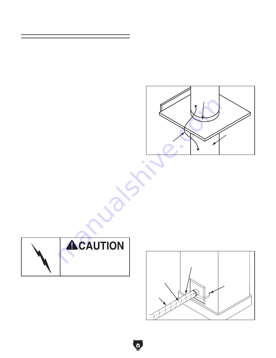
Attach  the  bare  ground  wire  to  each  stationary 
woodworking  machine  and  attach  to  the  dust 
collector  frame  with  a  ground  screw  as  shown 
in the figure

 below. Ensure that each machine is 

continuously grounded to the grounding terminal 
in your electric service panel.

External 

Ground Wire

Internal 

Ground Wire

Flex

Hose

Ground 

Screw

Figure 49. Flex-hose grounded to machine.

Plastic Blast

Gate 

Copper

Ground Wire

Metal Duct

Figure 48. Ground jumper wire when using  

plastic blast gates and metal duct.

Always guard against stat-

ic electrical build up by 

grounding all dust collec-

tion lines.

Summary of Contents for G0852

Page 1: ... JL WARNING NO PORTION OF THIS MANUAL MAY BE REPRODUCED IN ANY SHAPE OR FORM WITHOUT THE WRITTEN APPROVAL OF GRIZZLY INDUSTRIAL INC KB19640 PRINTED IN TAIWAN V1 08 19 MODEL G0852 1 5HP QUIET CYCLONE DUST COLLECTOR OWNER S MANUAL For models manufactured since 12 18 265752 ...

Page 2: ...ng grinding tool integrity and the usage of personal protective equipment The manufacturer will not be held liable for injury or property damage from negligence improper training machine modifications or misuse Some dust created by power sanding sawing grinding drilling and other construction activities contains chemicals known to the State of California to cause cancer birth defects or other repr...

Page 3: ...Run 21 SECTION 4 DESIGNING A SYSTEM 22 General 22 Duct Material 22 System Design 24 System Grounding 30 SECTION 5 OPERATIONS 31 Operation Overview 31 General Operation 31 Using Controls 32 SECTION 6 ACCESSORIES 33 SECTION 7 MAINTENANCE 35 Schedule 35 Emptying Replacing Filter Bag 35 Emptying Replacing Collection Bag 36 Washing Canister Filter 36 SECTION 8 SERVICE 37 Troubleshooting 37 Removing Rep...

Page 4: ...ade every effort to be exact with the instruc tions specifications drawings and photographs in this manual Sometimes we make mistakes but our policy of continuous improvement also means that sometimes the machine you receive is slightly different than shown in the manual If you find this to be the case and the difference between the manual and machine leaves you confused or unsure about something ...

Page 5: ...iliar with the names and locations of the features shown below to better understand the instructions in this manual Motor Cyclone Funnel Impeller Housing Swivel Caster Locking Base Stand Filter Bag Canister Filter Collection Bag Filter Brush Cleaning Handle Intake Barrel Swivel Caster Upper Cover ON OFF Switch 6 x 4 x 4 Dust Inlet Adapter ...

Page 6: ...imensions Type Wooden Pallet w Cardboard Box Content Machine Weight 280 lbs Length x Width x Height 49 x 30 x 40 in Must Ship Upright Yes Electrical Power Requirement 120V or 240V Single Phase 60 Hz Prewired Voltage 120V Full Load Current Rating 15A at 120V 7 5A at 240V Minimum Circuit Size 20A at 120V 15A at 240V Connection Type Cord Plug Power Cord Included Yes Power Cord Length 6 ft Power Cord ...

Page 7: ...ower Bags 1 Dust Collection Upper Bag Diameter 18 in Upper Bag Length 23 5 8 in Lower Bag Diameter 17 3 4 in Lower Bag Length 35 1 2 in Canister Information Number of Canister Filters 1 Canister Filter Diameter 17 in Canister Filter Length 26 in Impeller Information Impeller Type Radial Fin Impeller Size 12 1 2 in Impeller Blade Thickness 3 16 in Construction Upper Bag Clear Plastic Lower Bag Clea...

Page 8: ...id proof DANGEROUS ENVIRONMENTS Do not use machinery in areas that are wet cluttered or have poor lighting Operating machinery in these areas greatly increases the risk of accidents and injury MENTAL ALERTNESS REQUIRED Full mental alertness is required for safe operation of machin ery Never operate under the influence of drugs or alcohol when tired or when distracted For Your Own Safety Read Instr...

Page 9: ... moving parts or flying debris Make sure they are properly installed undamaged and working correctly BEFORE operating machine FORCING MACHINERY Do not force machine It will do the job safer and better at the rate for which it was designed NEVER STAND ON MACHINE Serious injury may occur if machine is tipped or if the cutting tool is unintentionally contacted STABLE MACHINE Unexpected movement dur i...

Page 10: ...in fire suppression system or have fire extinguisher nearby STATIC ELECTRICITY To reduce risk of fire or explosions caused by sparks from static electricity ground all ducting using grounding wire DUST ALLERGIES Dust from certain woods will cause an allergic reaction Make sure you know what type of wood dust you will be exposed to in case of an allergic reaction INTENDED USE Collecting the wrong m...

Page 11: ...operation and make sure it is connected to a power supply circuit that meets the specified circuit requirements For your own safety and protection of property consult an electrician if you are unsure about wiring practices or electrical codes in your area Note Circuit requirements in this manual apply to a dedicated circuit where only one machine will be running on the circuit at a time If machine...

Page 12: ...following size requirements Minimum Gauge Size 12 AWG Maximum Length Shorter is Better 50 ft Grounding Requirements This machine MUST be grounded In the event of certain malfunctions or breakdowns grounding reduces the risk of electric shock by providing a path of least resistance for electric current Figure 1 Typical 5 15 plug and receptacle Grounding Pin Neutral Hot 5 15 PLUG GROUNDED 5 15 RECEP...

Page 13: ...Remove wire nuts indicated in Figure 4 To convert Model G0852 to 240V 1 DISCONNECT MACHINE FROM POWER 2 Cut 120V 5 15 plug from power cord 3 Remove screw that secures junction box cover to motor see Figure 3 5 Use wire nuts to connect wires as indicated in Figure 5 Twist wire nuts onto their respec tive wires and wrap them with electrical tape so they will not come loose from vibration of motor op...

Page 14: ...ine and have resolved any issues between Grizzly or the shipping agent You MUST have the original pack aging to file a freight claim It is also extremely helpful if you need to return your machine later Unpacking SUFFOCATION HAZARD Keep children and pets away from plastic bags or packing materials shipped with this machine This machine presents serious injury hazards to untrained users Read throug...

Page 15: ...Front Lower Leg Left 1 I Leg Braces 2 J Collection Bag 1 K Filter Bag 1 L Exhaust Port 1 M Inlet Adapter 6 x 4 x 4 1 N Vacuum Hose 6 x 33 1 O Bag Clamp 19 1 P Bag Clamp 173 4 1 Q Hose Clamps 61 2 2 R Motor Impeller Housing w Switch Box 1 S Dust Intake Port 1 T Filter Brush Handle Assembly 1 U Swivel Casters Locking 2 V Swivel Casters 2 W Cyclone Funnel Gasket 1 X Upper Cover Gasket 1 Y Exhaust Por...

Page 16: ...Physical Environment The physical environment where the machine is operated is important for safe operation and lon gevity of machine components For best results operate this machine in a dry environment that is free from excessive moisture hazardous chemi cals airborne abrasives or extreme conditions Extreme conditions for this type of machinery are generally those where the ambient temperature r...

Page 17: ...ight front leg to base stand and finger tighten with 2 5 16 18 x 3 4 hex bolts and 2 5 16 fender washers see Figure 12 3 With bolt holes on front edge facing forward attach lower left front leg to base stand and finger tighten with 2 5 16 18 x 3 4 hex bolts and 2 5 16 fender washers see Figure 11 Note Lower left front leg has 2 extra threaded 5 16 18 bolt holes on front edge 2 Thread 2 3 swivel ca...

Page 18: ... to each brace see Figure 15 then finger tighten each upper leg with 2 5 16 18 x 3 4 hex bolts and 2 5 16 fender washers Figure 15 Upper legs installed 8 Place square gasket on intake barrel see Figure 16 inset then attach upper cover to intake barrel using 12 5 16 18 x 3 4 hex bolts and 12 5 16 fender washers see Figure 16 Tighten in star pattern Figure 14 Leg braces installed x 4 Leg Braces x 2 ...

Page 19: ... 3 4 hex bolts and 8 5 16 flat washers see Figure 18 Finger tighten for now Figure 17 Upper cover attached to upper legs x 8 Upper Cover Upper Legs Figure 19 Cyclone funnel attached to intake barrel Gasket Cyclone Funnel x 12 12 Place rubber gasket on cyclone funnel see Figure 19 inset then attach cyclone funnel to intake barrel using 12 5 16 18 x 1 hex bolts 24 5 16 fender washers and 12 5 16 18 ...

Page 20: ...mpeller housing using 2 5 16 18 x 3 4 hex bolts and 2 5 16 fender washers see Figure 21 Figure 21 Dust intake port exhaust port and switch box attached to motor impeller housing x 6 Exhaust Port x 2 Switch Box x 4 Motor Impeller Housing 18 Attach motor impeller housing using 4 5 16 18 x 3 4 hex bolts and 4 5 16 fender washers on base stand and 2 5 16 18 x 3 4 hex bolts and 2 5 16 fender washers on...

Page 21: ...4 22 Install filter brush handle assembly see Figure 26 inset over spindle block and upper cover then secure with 2 5 16 18 x 21 2 hex bolts and 2 5 16 flat washers see Figure 26 Figure 26 Filter brush handle assembly installed on canister filter x 2 Filter Brush Handle Assembly Figure 25 Attaching brush handle spindle block to canister filter brush spindle Canister Filter Brush Spindle Brush Hand...

Page 22: ...clamp see Figure 28 23 Place 18 x 235 8 filter bag around bottom of canister filter and secure with 19 metal clamp see Figure 27 Note Place clamp over foam gasket on can ister filter to prevent dust leaks Figure 29 Adapter attached to dust intake port Inlet Adapter Figure 28 Collection bag attached to collection bag lid 173 4 Clamp Collection Bag Lid Collection Bag Figure 27 Filter bag attached to...

Page 23: ...fuse connect machine to dust collection system and restrict airflow by partially closing blast gates to limit motor amperage draw dur ing test run Note If a dust collection system is not avail able restrict airflow by blocking one 4 port on the dust inlet adapter with a cap or a piece of wood 4 Stand away from intake port then press ON button on switch box see Figure 30 to turn dust collection mot...

Page 24: ...s Figure 31 Examples of plastic ducting components Duct Material You have many choices regarding main line and branch line duct material For best results use smooth metal duct for the main line and branch lines then use short lengths of flexible hose to connect each machine to the branch lines Plastic duct is also a popular material for home shops However be aware that there is a fire or explosion...

Page 25: ...ible is non resistant to abrasion and has a tendency to collapse in a negative pressure system We DO NOT recommend using dryer vent hose in your dust collection system If using flex hose you should choose one of the many types that are designed specifically for the movement of solid particles i e dust grains and plastics However the cost of specifically designed flexible duct can vary greatly Griz...

Page 26: ...ed some basic information here to get you started on a basic design If you have a large shop or plan to design a com plicated system we recommend doing additional research beyond this manual or seeking the help of an expert Step 2 Sketch Your Shop Layout When designing a successful dust collection sys tem planning is the most important step In this step sketch a basic layout of your shop including...

Page 27: ... If the machine has multiple dust ports the total CFM required is the sum of all ports Figure 37 Approximate required airflow for machines based on dust port size Machine Dust Port Size Approximate Required CFM 2 100 2 5 150 3 250 4 400 5 600 6 850 7 1200 8 1600 9 2000 10 2500 If the machine does not have a built in dust port use the following table to determine which size of dust port to install ...

Page 28: ...he machine as the branch line duct size will achieve the correct velocity in most appli cations However if the dust port on the machine is smaller than 4 make the branch line 4 and neck the line down right before the dust port Note Systems with powerful dust collectors work better if multiple blast gates are left open This also allows you to run two machines at once Experiment with different combi...

Page 29: ...0 4 600 5 700 5 800 6 900 6 1000 6 Adding duct work elbows branches and any other components to a duct line increases airflow resistance static pressure loss This resistance can be minimized by using rigid smooth duct and gradual curves as opposed to flexible duct and 90 elbows To help you think about this resistance imagine riding a bicycle in a tunnel that is an exact replica of your duct work I...

Page 30: ...of line connected to a dust collector router If the CFM for your static pressure loss is above the requirement of the machine connected to the end of that branch line then dust collection will most likely be successful Congratulations You ve just designed your own dust system Refer to the Accessories section on Page 33 to start buying the components necessary to make your system a reality If the C...

Page 31: ...Model Quantity 6 Rigid Duct at 20 G7364 4 4 Rigid Duct at 10 G6162 2 4 Flex Hose at 5 H7215 6 6 45 Y Branch G7353 6 4 45 Elbow G6167 6 Example Materials List After the system is designed create a materials list of all the items you will need to build your dust collection system This will make it easy when it comes time to purchase the materials Below is an example of some items that might be neede...

Page 32: ...t gates the system must still be grounded as mentioned above We recom mend inserting a continuous bare copper ground wire inside the entire duct system and attaching the wire to each grounded woodworking machine and dust collector Be sure that you extend the bare copper wire down all branches of the system Do not forget to con nect the wires to each other with wire nuts when two branches meet at a...

Page 33: ...perating this machine If you are not experienced with this type of machine WE STRONGLY RECOMMEND that you seek additional training outside of this manual Read books magazines or get formal training before beginning any proj ects Regardless of the content in this sec tion Grizzly Industrial will not be held liable for accidents caused by lack of training General Operation This cyclone dust collecto...

Page 34: ...nce Figure 51 Switch box controls Operating Filter Cleaning Brush Refer to Figure 52 and the following description to understand the filter cleaning brush functions Filter Cleaning Brush Handle Before each use turn filter cleaning brush handle to rotate internal brushes that knock caked on dust from the canis ter filter into the filter bag ON Button STOP Paddle Figure 52 Filter cleaning brush hand...

Page 35: ...igure 53 W1050 Dust Collection Basics Book Figure 55 Clear dust hose W1034 4 x 10 Dust Hose W1036 6 x 10 Dust Hose Spiral wire reinforced clear hose allows easy inspection for locating potential clogs in your duct system Uses RH fittings G6177 4 Metal Blast Gate G7340 5 Metal Blast Gate G7358 6 Metal Blast Gate Control airflow and resistance between machines These industrial blast gates can take t...

Page 36: ...and G2753 4 Bench Attachment G2754 4 Floor Attachment These attachments are indispensable for collect ing dust at machines without a port Designed for use with 4 flexible hose not included Figure 58 Dust collection attachments W1039 Universal Adapter This adapter provides a multitude of reducing options Simply cut off unneeded steps Outside diameter sizes include 1 2 21 2 3 4 5 and 6 Wall thicknes...

Page 37: ...before adjustments maintenance or service Dust exposure created while using machinery may cause cancer birth defects or long term respi ratory damage Always wear goggles and a NIOSH approved respirator when working with the dust col lection bags or canisters 3 Remove bag from canister filter and dispose of contents 4 Place new dust bag on filter 5 Re install bag clamp to secure Emptying Replacing ...

Page 38: ...ompressed air to clean or dry filter as this can spread fine dust into air and damage filter fibers 5 Allow filter to air dry only DO NOT use heat Washing Canister Filter Emptying Replacing Collection Bag Dispose of the collection bag when dust fills it about 3 4 full Immediately replace the bag if it develops a leak or becomes damaged If the bag gets overfilled the dust will be sucked into the in...

Page 39: ...lace centrifugal switch contact points if available 7 Test replace 8 Test replace 9 Test repair replace Machine seems underpowered 1 Motor overheated 2 Dust collection ducting problem 3 Canister filter clogged at fault 4 Dust collector undersized 5 Run capacitor at fault 6 Centrifugal switch contact points at fault 7 Motor bearings at fault 1 Allow motor to cool reset overload if necessary 2 Clear...

Page 40: ...d ports are incorrectly sized 9 The machine dust collection design is inadequate 10 Dust collector is undersized 1 Empty collection bag 2 Wash canister filter Page 36 replace canister filter Page 39 3 Remove ducting from dust collector inlet and unblock the restriction A plumbing snake may be necessary 4 Relocate dust collector closer to point of suction re secure ducts remove sharp bends Refer to...

Page 41: ...x 21 2 hex bolts securing filter cleaning handle assembly to canister filter then lift off handle see Figure 64 Figure 63 Filter bag components Bag Clamp Filter Bag Canister Filter Dust exposure created while using machinery may cause cancer birth defects or long term respi ratory damage Always wear goggles and a NIOSH approved respirator when working with the dust col lection bags or canisters Fi...

Page 42: ...to re assemble 5 Remove 5 5 16 18 x 3 4 hex bolts and 5 5 16 fender washers securing canister filter to bottom of upper cover see Figure 66 then remove canister filter with assistant s help Figure 66 Canister filter mounted to upper cover x 5 Upper Cover Canister Filter Figure 65 Removing brush spindle block from canister filter brush spindle Canister Filter Brush Spindle Brush Handle Spindle Bloc...

Page 43: ...nt at the time of printing but may not match your machine If you find this to be the case use the wiring diagram inside the motor junction box CAPACITORS INVERTERS Some capacitors and power inverters store an electrical charge for up to 10 minutes after being disconnected from the power source To reduce the risk of being shocked wait at least this long before working on capacitors EXPERIENCING DIF...

Page 44: ...nting but it may not match your machine Always use the wiring diagram inside the motor junction box Ground ON OFF SWITCH KEDU HY56 SHOCK HAZARD Disconnect power before working on wiring Hot Hot Ground 6 15 Plug As Recommended 220 VAC G Neutral Hot Ground 2 Run Capacitor 50 uF 250VAC Start Capacitor 300MFD 125VAC Bk Gn Wt Ground 4 2 3 1 3 1 LINE LOAD You MUST purchase additional components to conve...

Page 45: ...26 25 47 46 37 36 147 151 152 149 148 154 155 153 150 45 35 143 103 104 30 31 32 33 34 41 42 43 44 40 29 105 106 132 133 100 101 130 131 136 137 138 139 140 102 141 142 97 99 98 93 94 156 134 135 96 95 85 84 78 79 80 77 69 70 86 87 88 89 90 91 92 1 3 83 68 81 82 67 75 76 38 39 73 74 72 71 66 7 19 8 9 10 11 12 23 22 21 20 13 24 50 51 52 53 54 55 56 57 60 61 58 59 62 63 64 65 27 28 2 4 5 6 17 18 146...

Page 46: ...8 P0852068 IMPELLER COVER 25 P0852025 FENDER WASHER 5 16 69 P0852069 HEX BOLT 5 16 18 X 1 26 P0852026 HEX BOLT 5 16 18 X 3 4 70 P0852070 FLAT WASHER 5 16 27 P0852027 FENDER WASHER 5 16 71 P0852071 FLAT WASHER 5 16 28 P0852028 HEX BOLT 5 16 18 X 3 4 72 P0852072 LOCK NUT 5 16 18 29 P0852029 FRONT LOWER LEG 73 P0852073 HEX BOLT 5 16 18 X 1 30 P0852030 LEG BRACE 74 P0852074 FENDER WASHER 5 16 31 P0852...

Page 47: ...52110 STUD FT 1 4 20 X 7 147 P0852147 FILTER BRUSH GEAR 111 P0852111 BRUSH BRACKET 148 P0852148 FILTER BRUSH HANDLE 112 P0852112 FILTER BRUSH PVC 149 P0852149 HEX BOLT 5 16 18 X 1 113 P0852113 STUD FT 1 4 20 X 7 150 P0852150 LOCK NUT 5 16 18 114 P0852114 BRUSH BRACKET 151 P0852151 FLAT WASHER 5 16 115 P0852115 STUD FT 1 4 20 X 7 152 P0852152 HEX BOLT 5 16 18 X 2 1 2 116 P0852116 BRUSH BRACKET 153 ...

Page 48: ...y repair 10 Do not use without dust bags or filter in place 11 Do not connect cord to power supply with wet hands 12 Grasp and pull the plug not the cord when unplugging 13 Always wear a respirator when emptying bags 14 Do not modify machine in any way 15 Prevent unauthorized use by children or untrained users disable machine when unattended Motor 1 5 HP 115V 1 Ph 60 Hz Full Load Current Rating 15...

Page 49: ... metalworker ____ 0 2 Years ____ 2 8 Years ____ 8 20 Years ____20 Years 6 How many of your machines or tools are Grizzly ____ 0 2 ____ 3 5 ____ 6 9 ____10 7 Do you think your machine represents a good value _____Yes _____No 8 Would you recommend Grizzly Industrial to a friend _____Yes _____No 9 Would you allow us to use your name as a reference for Grizzly customers in your area Note We never use ...

Page 50: ...D LINE FOLD ALONG DOTTED LINE GRIZZLY INDUSTRIAL INC P O BOX 2069 BELLINGHAM WA 98227 2069 Place Stamp Here Name_______________________________ Street_______________________________ City______________State______Zip______ Send a Grizzly Catalog to a friend ...

Page 51: ... shall be tried in the State of Washington County of Whatcom We shall in no event be liable for death injuries to persons or property or for incidental contingent special or consequential damages arising from the use of our products To take advantage of this warranty contact us by mail or phone and give us all the details We will then issue you a Return Number which must be clearly posted on the o...

Page 52: ......

Reviews: