background image

-14-

Model G0798 (Mfd. Since 4/17)

Site Considerations

Weight Load

Refer to the 

Machine Data Sheet for the weight 

of your machine. Make sure that the surface upon 
which the machine is placed will bear the weight 
of the machine, additional equipment that may be 
installed on the machine, and the heaviest work-
piece that will be used. Additionally, consider the 
weight  of  the  operator  and  any  dynamic  loading 
that may occur when operating the machine.

Space Allocation

Consider  the  largest  size  of  workpiece  that  will 
be  processed  through  this  machine  and  provide 
enough space around the machine for adequate 
operator  material  handling  or  the  installation  of 
auxiliary equipment. With permanent installations, 
leave enough space around the machine to open 
or remove doors/covers as required by the main-
tenance  and  service  described  in  this  manual. 

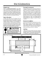
See below for required space allocation.

Physical Environment

The  physical  environment  where  the  machine  is 
operated is important for safe operation and lon-
gevity  of  machine  components.  For  best  results, 
operate this machine in a dry environment that is 
free  from  excessive  moisture,  hazardous  chemi-
cals,  airborne  abrasives,  or  extreme  conditions. 
Extreme conditions for this type of machinery are 
generally  those  where  the  ambient  temperature 
range  exceeds  41°–104°F;  the  relative  humidity 
range  exceeds  20%–95%  (non-condensing);  or 
the  environment  is  subject  to  vibration,  shocks, 
or bumps.

Electrical Installation

Place this machine near an existing power source. 
Make  sure  all  power  cords  are  protected  from 
traffic, material handling, moisture, chemicals, or 
other hazards. Make sure to leave enough space 
around  machine  to  disconnect  power  supply  or 
apply a lockout/tagout device, if required.

Lighting

Lighting  around  the  machine  must  be  adequate 
enough that operations can be performed safely. 
Shadows, glare, or strobe effects that may distract 
or impede the operator must be eliminated.

Children or untrained people 

may be seriously injured by 

this machine. Only install in an 

access restricted location.

Figure 3. Minimum working clearances.

= Power Connection

Wall

46"

108"

64"

22"

24½"

 30" Minimum

Summary of Contents for G0798

Page 1: ...ad and under stood for your own safety IMPORTANT Keep this update with the owner s manual for future reference For questions or help contact our Tech Support at 570 546 9663 or techsupport grizzly com READ THIS FIRST For questions or help with this product contact Tech Support at 570 546 9663 or techsupport grizzly com Model G0798 IMPORTANT UPDATE For Machines Mfd Since 4 20 and Owner s Manual Rev...

Page 2: ...am PADDLE SWITCH viewed from behind Left Motor Ground Ground 110 VAC 5 15 Plug Hot Neutral Ground Right Motor Terminal Dust Box Run Capacitor 30MFD 250VAC 9301A 21 20 125VAC 12 12 250VAC 1 2 3 4 JiHong Run Capacitor 30MFD 250VAC Replaces Page 26 ...

Page 3: ...or models manufactured since 4 17 COPYRIGHT FEBRUARY 2016 BY GRIZZLY INDUSTRIAL INC REVISED MAY 2017 MN WARNING NO PORTION OF THIS MANUAL MAY BE REPRODUCED IN ANY SHAPE OR FORM WITHOUT THE WRITTEN APPROVAL OF GRIZZLY INDUSTRIAL INC MC17817 PRINTED IN TAIWAN V3 05 17 ...

Page 4: ...ng grinding tool integrity and the usage of personal protective equipment The manufacturer will not be held liable for injury or property damage from negligence improper training machine modifications or misuse Some dust created by power sanding sawing grinding drilling and other construction activities contains chemicals known to the State of California to cause cancer birth defects or other repr...

Page 5: ...on Chart 12 Inventory 13 Site Considerations 14 Lifting Placing 15 Assembly 15 Power Connection 16 Test Run 17 SECTION 4 OPERATIONS 18 Operation 18 SECTION 5 ACCESSORIES 19 SECTION 6 MAINTENANCE 21 Schedule 21 Cleaning Protecting 21 Cleaning Dust Drawers 21 SECTION 7 SERVICE 22 Troubleshooting 22 Replacing Filters 23 SECTION 8 WIRING 24 Wiring Safety Instructions 24 Electrical Components 25 Wiring...

Page 6: ...ade every effort to be exact with the instruc tions specifications drawings and photographs in this manual Sometimes we make mistakes but our policy of continuous improvement also means that sometimes the machine you receive is slightly different than shown in the manual If you find this to be the case and the difference between the manual and machine leaves you confused or unsure about something ...

Page 7: ...tire manual BEFORE using machine Become familiar with the names and locations of the controls and features shown below to better understand the instructions in this manual Left Panel Suction Panels Downdraft Plate Right Panel Motor Access Door Dust Drawers ON OFF Paddle Switch Motor Access Door ...

Page 8: ...imensions Type Cardboard Box on Wood Pallet Content Machine Weight 349 lbs Length x Width x Height 64 x 28 x 34 in Must Ship Upright No Electrical Power Requirement 110V Single Phase 60 Hz Full Load Current Rating 12A Minimum Circuit Size 15A Connection Type Cord Plug Power Cord Included Yes Power Cord Length 6 ft Power Cord Gauge 14 AWG Plug Included Yes Included Plug Type 5 15 Switch Type Paddle...

Page 9: ...ze Length 61 1 2 in Table Size Width 21 1 2 in Floor to Table Height 29 1 2 in Table Load Capacity 440 lbs Construction Info Impeller Steel Table Formed Steel Table Inserts Stainless Steel Paint Type Finish Powder Coated Other Specifications Country of Origin Taiwan Warranty 1 Year Approximate Assembly Setup Time 15 Minutes Serial Number Location ID Label on Front of Machine Sound Rating 78 dB ISO...

Page 10: ...proof DANGEROUS ENVIRONMENTS Do not use machinery in areas that are wet cluttered or have poor lighting Operating machinery in these areas greatly increases the risk of accidents and injury MENTAL ALERTNESS REQUIRED Full mental alertness is required for safe operation of machin ery Never operate under the influence of drugs or alcohol when tired or when distracted For Your Own Safety Read Instruct...

Page 11: ...moving parts or flying debris Make sure they are properly installed undamaged and working correctly BEFORE operating machine FORCING MACHINERY Do not force machine It will do the job safer and better at the rate for which it was designed NEVER STAND ON MACHINE Serious injury may occur if machine is tipped or if the cutting tool is unintentionally contacted STABLE MACHINE Unexpected movement dur in...

Page 12: ...s intended and function safely Perform routine inspections and all necessary maintenance as indicated in owner s manual Never operate machine with damaged or worn parts Never operate machine with filters guards or covers removed USE FOR INTENDED PURPOSE This down draft table is designed to capture sparks and particles created while grinding certain metals DO NOT use it to capture materials made fr...

Page 13: ...he risk of these hazards avoid over loading the machine during operation and make sure it is connected to a power supply circuit that meets the specified circuit requirements Serious injury could occur if you connect machine to power before completing setup process DO NOT connect to power until instructed later in this manual For your own safety and protection of property consult an electrician if...

Page 14: ...ts longer and the gauge size gets smaller higher gauge numbers indicate smaller sizes Any extension cord used with this machine must be in good condition and contain a ground wire and matching plug receptacle Additionally it must meet the following size requirements Minimum Gauge Size 14 AWG Maximum Length Shorter is Better 50 ft Grounding Requirements This machine MUST be grounded In the event of...

Page 15: ...k aging to file a freight claim It is also extremely helpful if you need to return your machine later Unpacking SUFFOCATION HAZARD Keep children and pets away from plastic bags or packing materials shipped with this machine Discard immediately This machine presents serious injury hazards to untrained users Read through this entire manu al to become familiar with the controls and opera tions before...

Page 16: ... 12 Model G0798 Mfd Since 4 17 5mm Hardware Recognition Chart ...

Page 17: ...hipped with your machine Before beginning setup lay these items out and inventory them If any non proprietary parts are missing e g a nut or a washer we will gladly replace them or for the sake of expediency replacements can be obtained at your local hardware store Box 1 Figure 2 Qty A Main Housing Not Shown 1 B Suction Panels 2 C Handles 2 D Hardware 2 Phillips Head Screws M6 1 x 15 4 Flange Scre...

Page 18: ...s important for safe operation and lon gevity of machine components For best results operate this machine in a dry environment that is free from excessive moisture hazardous chemi cals airborne abrasives or extreme conditions Extreme conditions for this type of machinery are generally those where the ambient temperature range exceeds 41 104 F the relative humidity range exceeds 20 95 non condensin...

Page 19: ...able cabinet flat on floor Note We recommend sweeping the floor clean and laying down a piece of cardboard or a blanket to prevent scratching the paint during first step 2 Thread 6 foot pads into bottom of downdraft table as shown in Figure 5 3 Return downdraft table to upright position so it rests on foot pads 4 Ensure all six foot pads evenly touch floor Rotate individual footpads to adjust as n...

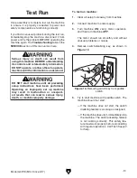
Page 20: ...crews Power Connection After you have completed all previous setup instructions and circuit requirements the machine is ready to be connected to the power supply To avoid unexpected startups or property dam age use the following steps whenever connecting or disconnecting the machine Connecting Power Figure 8 Connecting power 1 Turn the machine power switch OFF 2 Insert the power cord plug into a m...

Page 21: ...own in Figure 10 DO NOT start machine until all preceding setup instructions have been performed Operating an improperly set up machine may result in malfunction or unexpect ed results that can lead to serious injury death or machine property damage Serious injury or death can result from using this machine BEFORE understanding its controls and related safety information DO NOT operate or allow ot...

Page 22: ...ce workpiece on table 2 Place panels in upright position latching them with star knobs or folding side panels down when working on larger pieces that extend beyond the table 3 Turn downdraft table ON and perform opera tion see Figure 11 4 Turn downdraft table OFF when finished Figure 11 Typical grinding operation Side Panel This downdraft table features two separate 3 4 HP 110V single phase motors...

Page 23: ...nti Fatigue Mat features no slip tread for safety and comfort Open hole design allows liq uid to drain Perfect for wet and oily conditions Figure 12 Model T27576 Metal Mesh Filter T10493 4 Angle Grinder T10494 5 Angle Grinder T10495 6 Angle Grinder These Angle Grinders feature 3 position auxiliary handles and locking spindle buttons for easy disc changes The 4 model has a 5 8 bore and spins at 10 ...

Page 24: ...Safety Glasses T20452 Kirova Anti Reflective S Glasses H7194 Bifocal Safety Glasses 1 5 H7195 Bifocal Safety Glasses 2 0 H7196 Bifocal Safety Glasses 2 5 Figure 16 Assortment of basic eye protection T20451 T20452 T20502 T20503 H7194 H8214 Air Body Saw This Air Body Saw features a compact design and cuts sheet metal rods pipe and light plate at 5000 strokes per minute with a 3 8 stroke length It is...

Page 25: ...ly monitor and empty the dust drawers see Figure 20 Figure 20 Dust drawers Cleaning Protecting Cleaning the Model G0798 is relatively easy Vacuum excess dust and wipe off the remaining dust with a dry cloth To reduce risk of shock or accidental startup always disconnect machine from power before adjustments maintenance or service Wear safety glasses and a NIOSH approved respirator rated for the wa...

Page 26: ...nsure correct power supply voltage and circuit size 4 Ensure circuit is sized correctly and free of shorts Reset circuit breaker or replace fuse 5 Replace switch 6 Test replace 7 Test repair replace Machine stalls or is underpowered 1 Filter element at fault 2 Motor wired incorrectly 3 Motor overheated 4 Run capacitor at fault 1 Filter element at fault 2 Motor wired incorrectly 3 Motor overheated ...

Page 27: ...lockwise to remove lower filters see Figure 22 Figure 22 Lower filters secured by knobs Knobs To replace filters 1 DISCONNECT MACHINE FROM POWER 2 Remove table plate and all three support bars see Figure 21 Tools Needed Qty A Phillips Screwdriver 2 1 B Wrench 13mm 1 Figure 21 Support bars before removal Upper Filter Support Bars Lower Filter Wear safety glasses and a NIOSH approved respirator rate...

Page 28: ...nt at the time of printing but may not match your machine If you find this to be the case use the wiring diagram inside the motor junction box CAPACITORS INVERTERS Some capacitors and power inverters store an electrical charge for up to 10 minutes after being disconnected from the power source To reduce the risk of being shocked wait at least this long before working on capacitors EXPERIENCING DIF...

Page 29: ...ctrical Components Figure 25 Electrical component wiring To Right Side Motor Terminal Bar ON OFF Switch Box Power Cord Figure 23 ON OFF switch wiring ON OFF Switch To Terminal Bar Left Side Motor Figure 24 Left motor wiring Right Side Motor Figure 26 Right motor wiring ...

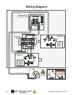
Page 30: ...FETY ON PAGE 24 Wiring Diagram PADDLE SWITCH viewed from behind Left Motor Ground Ground 110 VAC 5 15 Plug Hot Neutral Ground Right Motor Terminal Bar Run Capacitor 30MFD 250VAC 9301A 21 20 125VAC 12 12 250VAC 1 2 3 4 JiHong Run Capacitor 30MFD 250VAC ...

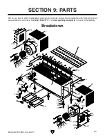
Page 31: ...10 13 48 22 47 24 10 50 49 39 36 53 54V2 8 2V2 9 15 14 11 10 13 10 50 49 7V2 1 5 6 7V2 8 2V2 5 6 55 56 7V2 7V2 55 56 Breakdown SECTION 9 PARTS We do our best to stock replacement parts when possible but we cannot guarantee that all parts shown are available for purchase Call 800 523 4777 or visit www grizzly com parts to check for availability ...

Page 32: ...798014 HEX BOLT 1 4 20 X 3 4 39 P0798039 MOTOR CORD 16G 3W 100 RIGHT 15 P0798015 MOTOR 3 4HP 110V 1 PH 40 P0798040 CAP SCREW 1 2 13 X 4 16V2 P0798016V2 MAIN HOUSING V2 11 16 41 P0798041 RUBBER FOOT PAD 17 P0798017 RIGHT PANEL 42 P0798042 FENDER WASHER 1 2 18 P0798018 STAR KNOB 1 4 X 3 8 43 P0798043 LOCK NUT 1 2 13 19 P0798019 PHLP HD SCR 10 24 X 3 8 44 P0798044 HEX NUT 1 2 13 20 P0798020 FLANGE SC...

Page 33: ... Prevent unauthorized use by children or untrained users WARNING COPYRIGHT GRIZZLY INDUSTRIAL INC DO NOT REPRODUCE OR CHANGE THIS ARTWORK Grizzly will not accept labels changed without approval If ges are required contact us immediately at manuals grizzly com achine Labels A Scale 1 1 unless otherwise noted Labels MUST be made of chemical resistant material PANTONE 485 C or RAL 3001 PANTONE 151 C ...

Page 34: ... metalworker ____ 0 2 Years ____ 2 8 Years ____ 8 20 Years ____20 Years 6 How many of your machines or tools are Grizzly ____ 0 2 ____ 3 5 ____ 6 9 ____10 7 Do you think your machine represents a good value _____Yes _____No 8 Would you recommend Grizzly Industrial to a friend _____Yes _____No 9 Would you allow us to use your name as a reference for Grizzly customers in your area Note We never use ...

Page 35: ...D LINE FOLD ALONG DOTTED LINE GRIZZLY INDUSTRIAL INC P O BOX 2069 BELLINGHAM WA 98227 2069 Place Stamp Here Name_______________________________ Street_______________________________ City______________State______Zip______ Send a Grizzly Catalog to a friend ...

Page 36: ......

Page 37: ... shall be tried in the State of Washington County of Whatcom We shall in no event be liable for death injuries to persons or property or for incidental contingent special or consequential damages arising from the use of our products To take advantage of this warranty contact us by mail or phone and give us all the details We will then issue you a Return Number which must be clearly posted on the o...

Page 38: ......

Reviews: