background image

-28-

Model G0762 (Mfd. Since 5/14)

Cutting tools are sharp and 

can easily cause laceration 

injuries. Always protect 

your hands with leather 

gloves or shop rags when 

handling cutting tools.

Installing Tooling

Tools Needed 

Qty

Wrench 19mm ................................................... 1

To install tooling:

1.  DISCONNECT MACHINE FROM POWER!

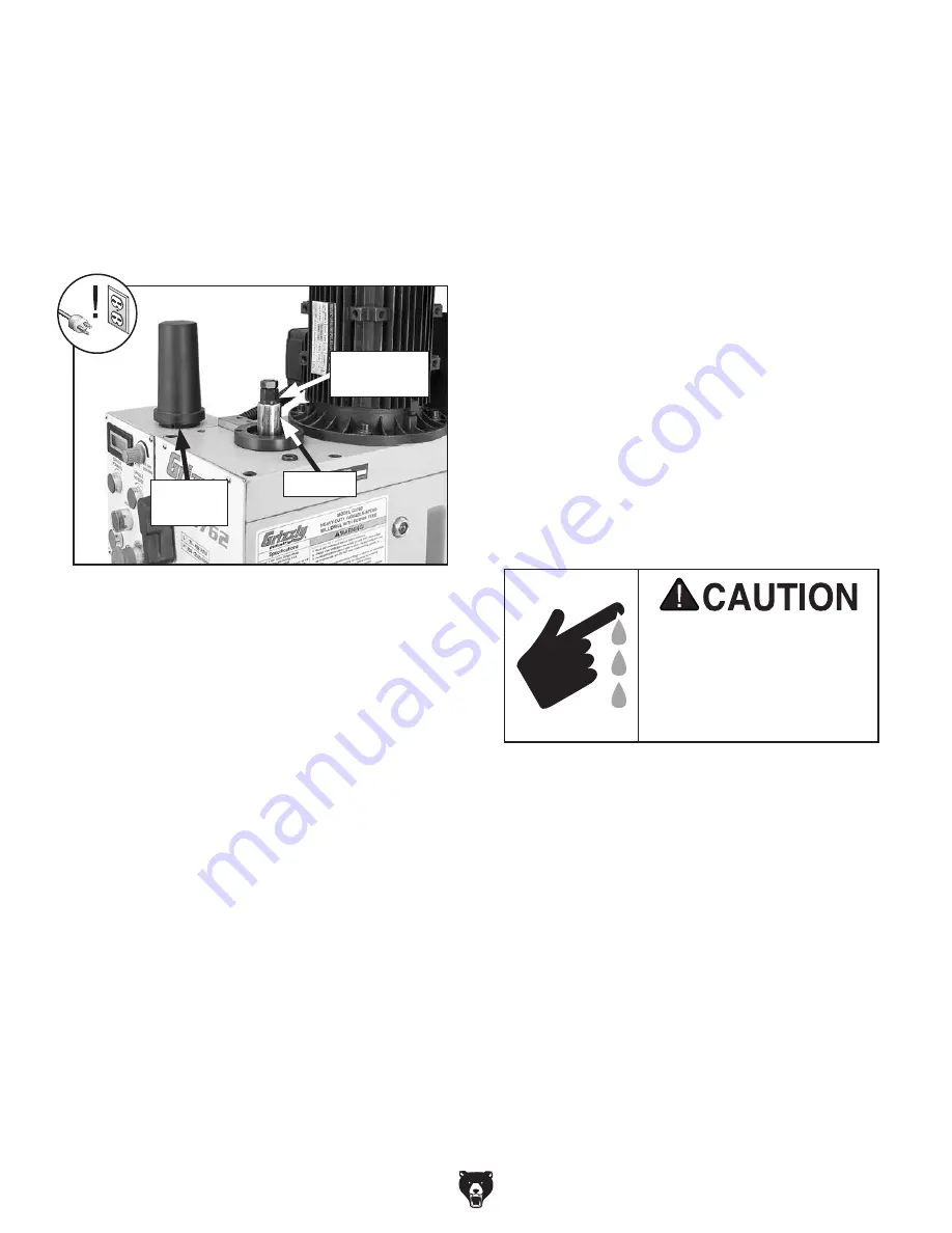
2.  Remove drawbar cap, as shown in Figure 31.

3.  Position  tool  alignment  slot  (see  Figure  30 

on  previous  page)  with  pin  inside  spindle, 
then insert tooling into spindle until it contacts 
drawbar.


Note:  Height of drawbar inside spindle can 
be changed by rotating adjustment nut (see 

Figure 31).

4.  Working  from  the  top,  thread  drawbar  by 

hand  into  tooling  until  it  is  snug,  then  use 
wrench to tighten it.


Note:  Do not overtighten drawbar. 
Overtightening makes tool removal difficult 
and will damage arbor and threads.

5.  Re-install drawbar cap.

Removing Tooling

Tools Needed 

Qty

Wrench 19mm ................................................... 1
Brass Head or Dead Blow Hammer .................. 1

To remove tooling:

1.  DISCONNECT MACHINE FROM POWER!

2.  Remove drawbar cap.

3.  Unthread drawbar from tooling one full rota-

tion.


Note:  Do not fully unthread tooling from 
drawbar or the drawbar and tool threads 
could be damaged in the next step.

4.  Tap  top  of  drawbar  with  hammer  to  unseat 

taper.

5.  Hold  onto  tooling  with  one  hand  and  fully 

unthread drawbar to remove tooling.

Figure 31. Drawbar components.

Drawbar

Cap

Drawbar

Adjustment 

Nut

Summary of Contents for G0762

Page 1: ...OWNER S MANUAL For models manufactured since 5 14 COPYRIGHT JUNE 2014 BY GRIZZLY INDUSTRIAL INC WARNING NO PORTION OF THIS MANUAL MAY BE REPRODUCED IN ANY SHAPE OR FORM WITHOUT THE WRITTEN APPROVAL O...

Page 2: ...g grinding tool integrity and the usage of personal protective equipment The manufacturer will not be held liable for injury or property damage from negligence improper training machine modifications...

Page 3: ...th Stop 24 Headstock Movement 25 Raising Lowering Headstock 25 Tilting Headstock 25 Table Travel 26 Graduated Dials 26 X Axis Handwheel 26 Y Axis Handwheel 26 X Axis Power Feed 27 Installing Removing...

Page 4: ...ind our machines If you have any questions or need help use the information below to contact us Before contacting please get the serial number and manufacture date of your machine This will help us he...

Page 5: ...Cap Headstock Tilt Scale Z Axis Lock Dovetail Column Electrical Cabinet Downfeed Selector Knob Spindle Quill Lock Fine Downfeed Handwheel Depth Stop Scale Gearbox Lever Power Feed Stop X Axis Table L...

Page 6: ...e 1 Control panel and spindle speed controls A H G F B C E D Refer to Figures 1 5 and the following descrip tions to become familiar with the basic controls of this machine To reduce your risk of seri...

Page 7: ...Stop and Scale Shows the position of the spindle and can limit spindle travel Figure 3 Downfeed controls P O N L M K Q ON OFF Light Illuminates when the unit is turned ON R Directional Lever Controls...

Page 8: ...Height 35 x 36 x 46 in Electrical Power Requirement 220V Single Phase 60Hz Full Load Current Rating 6 2A Minimum Circuit Size 15A Power Cord Included Yes Power Cord Length 5 ft Power Cord Gauge 14 AWG...

Page 9: ...s 75 2500 RPM Quill Diameter 3 in Drawbar Thread Size 7 16 20 Drawbar Length 17 3 4 in Spindle Bearings High Precision P5 Tapered Roller Bearings Construction Spindle Housing Quill Cast Iron Table Cas...

Page 10: ...of DANGEROUS ENVIRONMENTS Do not use machinery in areas that are wet cluttered or have poor lighting Operating machinery in these areas greatly increases the risk of accidents and injury MENTAL ALERTN...

Page 11: ...duce accidental contact with moving parts or flying debris Make sure they are properly installed undamaged and working correctly FORCING MACHINERY Do not force machine It will do the job safer and bet...

Page 12: ...utter You can be severely cut or have your fingers amputated from contact with the rotating cutter You can be blinded or struck with great force by broken cutting tools metal chips workpieces or adjus...

Page 13: ...ting or fire may result especially if connected to an undersized circuit To reduce the risk of these hazards avoid over loading the machine during operation and make sure it is connected to a power su...

Page 14: ...indicate smaller sizes Any extension cord used with this machine must contain a ground wire match the required plug and receptacle and meet the following require ments Minimum Gauge Size 14 AWG Maximu...

Page 15: ...satisfied with the condi tion of your shipment inventory the contents Unpacking SUFFOCATION HAZARD Keep children and pets away from plastic bags or packing materials shipped with this machine Discard...

Page 16: ...1 Ea F Hex Wrenches 2 5 3 4 5 10mm 1 Ea G Drift Key 1 H Drill Chuck w Chuck Key B16 1 13mm 1 I Spindle Sleeve R 8 x MT 3 1 J Drill Chuck Arbor R 8 x B16 1 K Spindle Sleeve MT 3 x MT 2 1 L Handwheels 2...

Page 17: ...paint scraper optional Basic steps for removing rust preventative 1 Put on safety glasses 2 Coat the rust preventative with a liberal amount of cleaner degreaser then let it soak for 5 10 minutes 3 W...

Page 18: ...tion Physical Environment The physical environment where the machine is operated is important for safe operation and lon gevity of machine components For best results operate this machine in a dry env...

Page 19: ...and place machine Figure 11 Recommended lifting sling position Bench Mounting Figure 13 Example of a Direct Mount setup Machine Base Workbench Lag Screw Flat Washer Another option is a Direct Mount s...

Page 20: ...h 2 M8 1 25 x 20 cap screws see Figure 14 3 Slide compression spring onto right end of X axis leadscrew as shown in Figure 15 This will keep handwheel disengaged when using power feed Figure 15 Compre...

Page 21: ...t to separate the assembly If you would like to use a different chuck in the future we recommend obtaining a new arbor Important DO NOT install the drill chuck and arbor into the spindle until AFTER t...

Page 22: ...RE understanding its controls and related safety information DO NOT operate or allow others to operate machine until the information is understood To test run mill drill 1 Clear all setup tools away f...

Page 23: ...button Spindle should rotate counterclockwise as viewed from top 12 Press EMERGENCY STOP button and wait for spindle to completely stop In the next step you will verify that EMERGENCY STOP button saf...

Page 24: ...it is still warm refer to Lubrication on Page 32 for detailed instructions This ensures you start opera tion with clean headstock oil The spindle break in of the machine is now com plete The spindle...

Page 25: ...ng outside of this manual Read books magazines or get formal training before beginning any proj ects Regardless of the content in this sec tion Grizzly Industrial will not be held liable for accidents...

Page 26: ...d handwheel to raise and lower spindle 5 Tighten quill lock lever The coarse downfeed handle and fine downfeed handwheel see Figure 20 move the spindle up and down for various milling drilling operati...

Page 27: ...shown in Figure 22 to adjust headstock height 4 Tighten Z axis lock levers to secure setting Tilting Headstock 1 DISCONNECT MACHINE FROM POWER 2 Loosen the three locking hex nuts see Figures 23 24 3...

Page 28: ...ial for a relative starting point Figure 26 Graduated dial and thumb screw Thumb Screw Graduated Dial X Axis Handwheel Tool Needed Qty Hex Wrench 5mm 1 To use X axis handwheel 1 Loosen both X axis tab...

Page 29: ...and use directional lever to select direction of table movement 6 Flip ON OFF switch up to turn power feed ON 7 Adjust speed dial to move table at required feed rate for your operation Note Power feed...

Page 30: ...gure 31 4 Working from the top thread drawbar by hand into tooling until it is snug then use wrench to tighten it Note Do not overtighten drawbar Overtightening makes tool removal difficult and will d...

Page 31: ...ing the spindle speed These sources also provide a wealth of additional information about the variables that affect cutting speed and they are a good educational resource Also there are a large number...

Page 32: ...pressure pump Figure 37 High pressure oil cans H7616 H7617 G7156 4 35 8 Precision Milling Vise G7154 5 41 2 Precision Milling Vise G7155 6 55 8 Precision Milling Vise Swiveling Milling Vises feature...

Page 33: ...due build up around the moving parts Use a brush and shop vacuum to remove chips and debris from the working sur faces of the mill drill Never blow off the mill drill with compressed air as this will...

Page 34: ...il 2 DISCONNECT MACHINE FROM POWER 3 Remove fill plug see Figure 38 4 Place a 1 gallon or larger drain pan on table under headstock 5 Remove drain plug see Figure 39 from underneath headstock and allo...

Page 35: ...tion area continue pumping the oil can until the oil runs clear When finished wipe away the excess oil Figure 40 Location of handwheel ball oilers Ball Oilers Table Column Ways Lube Type Model SB1365...

Page 36: ...to evenly distribute the oil Table Leadscrews Lube Type Model SB1365 or ISO 68 Equivalent Lube Amount Thin Coat Lubrication Frequency 40 hrs of Operation Move the table as necessary to access the enti...

Page 37: ...om ponents see Figure 45 When dry use a brush to apply a thin coat of grease to the teeth then raise lower the quill sev eral times to evenly distribute the grease Note Re apply oil to the quill outsi...

Page 38: ...is overloaded 1 Feed rate cutting speed too fast 2 Wrong tooling 3 Machine undersized for task or tooling incorrect for task 4 Motor overheated 5 Motor wired incorrectly 6 Motor bearings at fault 7 M...

Page 39: ...ar down 1 Tighten table locks 2 Properly clamp workpiece on table or in vise 3 Set spindle speed correctly Page 29 or use a slower feed rate 4 Fully retract spindle and lower headstock This increases...

Page 40: ...7 and tighten the opposing screw the same amount to move the gib while at the same time using the handwheels to move the table until you feel a slight drag in that path of movement Adjusting Leadscrew...

Page 41: ...gloves and safety glasses when adjusting return spring ten sion To adjust return spring tension 1 DISCONNECT MACHINE FROM POWER 2 Wipe off any oil on spring cover so it does not slip when you hold it...

Page 42: ...iagrams is current at the time of printing but may not match your machine If you find this to be the case use the wiring diagram inside the motor junction box CAPACITORS INVERTERS Some capacitors and...

Page 43: ...Model G0762 Mfd Since 5 14 41 Fan Junction Box Motor Junction Box Electrical Cabinet Control Panel RPM Sensor Wiring Overview Figure 50 Electrical component wiring overview...

Page 44: ...IC CC 53 FM F R CC R L1 S L1 SU P24 OUT NO CC 24 FLB FLA FLC RC RY V T2 W T3 U T1 PB PO PA PC RES S1 S2 5 8 1 4 6 7 2 3 Right Side Left Side Master Power Switch Master Power Switch 4 0 2 2 3 3 4 4 4 5...

Page 45: ...Model G0762 Mfd Since 5 14 43 Figure 51 Electrical cabinet...

Page 46: ...GND 5 5 4 4 PE PE PE PE PE U1 U1 U1 V1 V1 V1 W1 W1 W1 L3 N3 Z1 V1 V2 U2 U1 Z2 W1 W2 RPM Sensor XINGHUD WXD3 12 2W 4K 5 Minger LA125HBE 101C Minger LA125 HD 206A Power Button Minger LA125HBE 101C Minge...

Page 47: ...Model G0762 Mfd Since 5 14 45 READ ELECTRICAL SAFETY ON PAGE 40 Figure 52 Control panel with circuit board Figure 54 Motor fan junction box Figure 53 Motor junction box...

Page 48: ...8 69 70 71 72 73 3 74 75 76 77 78 79 80 81 82 83 84 85 86 87 88 89 90 91 92 93 94 95 96 97 98 99 100 101 102 103 104 105 106 107 108 109 110 111 112 113 114 115 116 119 121 120 122 117 7 7 7 8 48A Hea...

Page 49: ...DEPTH POINTER 16 P0762016 SET SCREW M10 1 5 X 10 DOG PT 67 P0762067 SPANNER NUT LOCK WASHER 30MM 17 P0762017 KEY 6 X 6 X 28 68 P0762068 SPANNER NUT M30 1 5 18 P0762018 OIL FILL PLUG 3 8 ZG 69 P0762069...

Page 50: ...113 P0762113 CAP SCREW M6 1 X 16 100 P0762100 SET SCREW M5 8 X 12 114 P0762114 CAP SCREW M4 7 X 16 101 P0762101 ROLL PIN 3 X 12 115 P0762115 SHAFT SEAL 12 X 22 X 8 102 P0762102 KEY 8 X 8 X 20 116 P076...

Page 51: ...206 206 206 206 206 207 207 207 207 208 209 209 283 210 210 211 211 212 212 214 215 216 217 218 218 219 219 220 220 221 221 222 223 224 225 226 227 229 234 231 231 232 233 235 236 237 238 239 241 242...

Page 52: ...TMENT HANDLE M8 1 25 274 2 P0762274 2 DIRECTION CONTROL HANDLE 223 P0762223 LOCK WASHER 16MM 274 3 P0762274 3 SPEED CONTROL KNOB 224 P0762224 FLAT WASHER 16MM 274 4 P0762274 4 ON OFF SWITCH 225 P07622...

Page 53: ...Model G0762 Mfd Since 5 14 51 Electrical Component Diagram Electrical Cabinet Control Panel 301 302 303 304 304 304 305 306 307 308 309 310 312 312 313 314 315 316 317...

Page 54: ...CIRCUIT BREAKER CHINT NS2 25 20 25A 312 P0762312 SPINDLE SWITCH MINGER LA125HBE 101C 304 P0762304 CONTACTOR SIEMENS 3TB41 220V 313 P0762313 POWER BUTTON MINGER LA125 HD 206A 305 P0762305 CIRCUIT BREAK...

Page 55: ...0762403 FLAT WASHER 12MM 411 P0762411 HEX WRENCH 10MM 404 P0762404 HEX NUT M12 1 75 412 P0762412 HEX WRENCH 5MM 405 P0762405 DRILL CHUCK B16 W CHUCK KEY 413 P0762413 HEX WRENCH 4MM 405 1 P0762405 1 DR...

Page 56: ...3 P0762503 CONTROL PANEL LABEL 508 P0762508 GRIZZLY PUTTY TOUCH UP PAINT 504 P0762504 ELECTRICITY LABEL 509 P0762509 GRIZZLY GREEN TOUCH UP PAINT 505 P0762505 DISCONNECT POWER LABEL 510 P0762510 GRIZZ...

Page 57: ...metalworker ____ 0 2 Years ____ 2 8 Years ____ 8 20 Years ____20 Years 6 How many of your machines or tools are Grizzly ____ 0 2 ____ 3 5 ____ 6 9 ____10 7 Do you think your machine represents a good...

Page 58: ...LINE FOLD ALONG DOTTED LINE GRIZZLY INDUSTRIAL INC P O BOX 2069 BELLINGHAM WA 98227 2069 Place Stamp Here Name_______________________________ Street_______________________________ City______________S...

Page 59: ...shall be tried in the State of Washington County of Whatcom We shall in no event be liable for death injuries to persons or property or for incidental contingent special or consequential damages arisi...

Page 60: ......

Reviews: