Grizzly G0452 Owner'S Manual Download Page 26

-24-

Model G0452/P/Z (Mfg. Since 08/12)

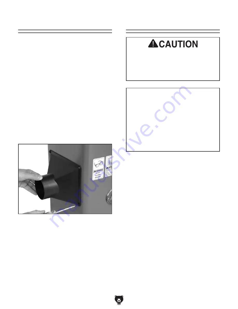
Figure 25. Dust port installation.

Components and Hardware Needed: 

Qty

Dust Port ........................................................... 1
Phillips Head Screws M5-.8 x 15 ....................... 4
Flat Washers 5mm ............................................ 4 

Tools Needed: 

Qty

Phillips Head Screwdriver .................................. 1

To install the dust port:

Note: If you choose to not use a dust collection 
system, don't install the dust port. Chips will build 
up inside the cabinet and clog.

1.  Place the dust port over the dust vent in the 

side of the cabinet.

2.  Use the M5-.8 x 15 Phillips head screws and 

flat  washers  to  secure  the  dust  port  to  the 
cabinet (see 

Figure 25).

3.  Attach to dust collection system.

Dust Port

Dust Collection

To connect a dust collection hose:

1.  Fit  the  4"  dust  hose  over  the  dust  port,  as 

shown in 

Figure 25, and secure in place with 

a hose clamp.

2.  Tug the hose to make sure it does not come 

off. 

Note:  A tight fit is necessary for proper 

performance.

This machine creates a lot of wood chips/

dust during operation. Breathing airborne 

dust on a regular basis can result in perma-

nent respiratory illness. Reduce your risk 

by wearing a respirator and capturing the 

dust with a dust collection system.

Recommended CFM at Dust Port: 400 CFM
Do not confuse this CFM recommendation with 
the rating of the dust collector. To determine the 
CFM at the dust port, you must consider these 
variables: (1) CFM rating of the dust collector, 
(2) hose type and length between the dust col-
lector and the machine, (3) number of branches 
or wyes, and (4) amount of other open lines 
throughout the system. Explaining how to cal-
culate these variables is beyond the scope of 
this manual. Consult an expert or purchase a 
good dust collection "how-to" book.

Summary of Contents for G0452

Page 1: ...WARNING NO PORTION OF THIS MANUAL MAY BE REPRODUCED IN ANY SHAPE OR FORM WITHOUT THE WRITTEN APPROVAL OF GRIZZLY INDUSTRIAL INC PC7250 PRINTED IN CHINA MODEL G0452 Series 6 x 46 MOBILE JOINTER OWNER S...

Page 2: ...g grinding tool integrity and the usage of personal protective equipment The manufacturer will not be held liable for injury or property damage from negligence improper training machine modifications...

Page 3: ...Switch 25 Handwheels 25 Infeed Table Lever 26 Setting Outfeed Table Height 26 For Models G0452 G0452P 26 For Model G0452Z 27 Test Run 28 Recommended Adjustments 28 SECTION 4 OPERATIONS 29 Operation O...

Page 4: ...nual If you find this to be the case and the difference between the manual and machine leaves you confused or unsure about something check our website for an updated version We post current manuals an...

Page 5: ...Mfg Since 08 12 3 Identification Outfeed Table Fence Cutterhead Guard Fence Lock Fence Adjustment Knob ON OFF Switch Infeed Table Infeed Table Lever Locking Foot Pedal Dust Port Outfeed Table Handwhe...

Page 6: ...Width side to side Depth front to back Height 21 x 16 x 29 Electrical Power Requirement 120V Single Phase 60 Hz 120V 240V Single Phase 60 Hz Full Load Current Rating 13A 15A at 240V 7 5A at 120V Switc...

Page 7: ...kpiece Thickness 1 2 in Maximum Rabbeting Depth 1 2 in Number of Cuts Per Minute 14 400 19 200 Fence Information Fence Length 35 in Fence Width 11 2 in Fence Height 5 in Fence Stop 45 90 and 135 deg C...

Page 8: ...ever Table Movement Type Dovetailed Ways Construction Body Assembly Cast Iron Cabinet Pre Steel Cabinet Fence Assembly Cast Iron Guard Die Cast Metal Table Precision Ground Cast Iron Paint Powder Coat...

Page 9: ...proof DANGEROUS ENVIRONMENTS Do not use machinery in areas that are wet cluttered or have poor lighting Operating machinery in these areas greatly increases the risk of accidents and injury MENTAL AL...

Page 10: ...h moving parts or flying debris Make sure they are properly installed undamaged and working correctly BEFORE operating machine FORCING MACHINERY Do not force machine It will do the job safer and bette...

Page 11: ...otation If the outfeed table is set too low the workpiece may rock against the cutterhead If the table is set too high the workpiece may hit the outfeed table and get stuck over the cutterhead INSPECT...

Page 12: ...wing section For your own safety and protection of property consult an electrician if you are unsure about wiring practices or electrical codes in your area Note The circuit requirements listed in thi...

Page 13: ...wo prong outlets do not meet the grounding requirements for this machine Do not modify or use an adapter on the plug provided if it will not fit the outlet have a qualified electrician install the pro...

Page 14: ...rent Carrying Prongs 6 15 PLUG GROUNDED 6 15 RECEPTACLE For 240V operation The plug specified under Circuit Requirements for 240V on the previous page has a grounding prong that must be attached to th...

Page 15: ...nce the manual was printed Use the diagram included on the motor junction box cover instead Items Needed Qty Phillips Head Screwdriver 2 1 Electrical Tape As Needed Wire Nut 14 AWG x 3 1 Plug 6 15 1 5...

Page 16: ...cult When you are completely satisfied with the condi tion of your shipment inventory the contents Unpacking SUFFOCATION HAZARD Keep children and pets away from plastic bags or packing materials shipp...

Page 17: ...inventory A D B G E F H I J C L K M N O NOTICE If you cannot find an item on this list care fully check around inside the machine and packaging materials Often these items get lost in packaging mater...

Page 18: ...lastic paint scraper optional Basic steps for removing rust preventative 1 Put on safety glasses 2 Coat the rust preventative with a liberal amount of cleaner degreaser then let it soak for 5 10 minut...

Page 19: ...nt The physical environment where the machine is operated is important for safe operation and lon gevity of machine components For best results operate this machine in a dry environment that is free f...

Page 20: ...4 Install the M10 1 5 x 55 hex bolts flat wash ers and hex nuts through the front of the locking foot pedal assembly as shown in Figure 12 2 Place the locking foot pedal assembly onto the cross brace...

Page 21: ...tant lift the jointer onto the cabinet 3 Align the three bolt holes on the jointer with the three holes on the cabinet Figure 13 4 Using the 8mm hex wrench secure the jointer to the cabinet with the M...

Page 22: ...lt loosen the set screws on the end of the motor pulley and align the motor pulley with the cutterhead pulley If needed the motor can be loosened and moved in or out to bring the motor pulley into ali...

Page 23: ...Hex Wrench 6mm 1 To install the carriage mounting bracket 1 Align the locating pins on the back of the car riage mounting bracket with the sockets on the jointer table see Figure 17 Carriage Mounting...

Page 24: ...ge assembly to the carriage mounting bracket see Figure 19 Fence Carriage Assembly Figure 20 Installing fence assembly To install the fence carriage assembly 1 Use the M8 1 25 x 25 cap screws lock was...

Page 25: ...nd add a half turn to the spring knob and test again Repeat this step as necessary Figure 23 Setting torsion spring knob 2 Wind the torsion spring knob back counter clockwise a half turn and slide the...

Page 26: ...5 and secure in place with a hose clamp 2 Tug the hose to make sure it does not come off Note A tight fit is necessary for proper performance This machine creates a lot of wood chips dust during opera...

Page 27: ...7 Cord locations 2 Plug the motor cord into the back of the switch box then secure the loose cords with the hold downs shown in Figure 27 Motor Cord Hold Downs Power Cord Power Switch Components and H...

Page 28: ...o set the outfeed table height for knives 1 Place a straightedge on the outfeed table so it extends over the cutterhead 2 Rotate the cutterhead pulley until one of the knives is at top dead center TDC...

Page 29: ...f your outfeed table is correctly set no adjustments are necessary If the insert lifts the straightedge off the table or is below the straightedge loosen outfeed table lock and adjust table height unt...

Page 30: ...instructions for these adjustments can be found in SECTION 7 SERVICE on Page 42 Factory adjustments that should be verified 1 Knife Settings Page 44 2 Insert Settings Page 46 3 Depth Scale Calibration...

Page 31: ...any proj ects Regardless of the content in this sec tion Grizzly Industrial will not be held liable for accidents caused by lack of training This overview gives you the basic process that happens duri...

Page 32: ...tment must be made to safely and efficiently use the jointer DO NOT set the infeed table depth greater than 1 16 on your first pass and never greater than 1 8 when rab beting To adjust the infeed tabl...

Page 33: ...the cutting depth and make additional passes Figure 40 Correct and incorrect grain alignment to cutterhead Stock Inspection and Requirements Remove foreign objects from the stock Make sure that any s...

Page 34: ...stock see Figures 43 44 to prepare it for thickness plan ing on a planer Squaring stock involves four steps performed in the order below 1 Surface Plane on the Jointer The concave face of the workpiec...

Page 35: ...r pressure on the outfeed end of the workpiece while feeding and repeat the same action with your trailing hand when it gets within 4 of the cutterhead To keep your hands safe DO NOT let them get clos...

Page 36: ...that is over the outfeed table Now focus your pressure on the outfeed end of the workpiece while feeding and repeat the same action with your trailing hand when it gets within 4 of the cutterhead To...

Page 37: ...of the cutterhead lift it up and over the cutterhead and place the push block on the portion of the workpiece that is on the outfeed table Now focus your pressure on the outfeed end of the workpiece...

Page 38: ...ead guard is removed attempting any other cut besides a rabbet directly exposes the operator to the moving cutterhead Always replace the cutterhead guard after rabbet cutting 6 Start the jointer 7 Wit...

Page 39: ...d a razor hone to your planer and jointer knives with this hand held sharpening device This handy tool sharpens flat and beveled surfaces quickly and easily Great for touch ups W1212 Woodstock Jointer...

Page 40: ...sliding friction and hangups This product also reduces rust and pre vents resin build up Figure 55 Table gel and spray H9876 6 x 5 8 x 1 8 HSS Jointer Knives These 6 x 5 8 x 1 8 Jointer Knives are mad...

Page 41: ...5 extra inserts T handle wrench Torx bits and spare insert screws Has an incredible finish and is comparable to Byrd cutterheads in quality of cut as well as the quality of the cutterhead itself Figur...

Page 42: ...s and heights depths Features stainless steel shock resistant construc tion and a dust proof display An absolute treat for the perfectionist Figure 64 Grizzly Dial Calipers T20501 Face Shield Crown Pr...

Page 43: ...de the V belt must be in good condition free from cracks fraying and wear and properly aligned and tensioned refer to the instructions on Page 20 Since all bearings are sealed and permanently lubricat...

Page 44: ...load on circuit 2 Increase wire sizes or reduce length of the circuit Motor overheats 1 Motor overloaded during operation 2 Air circulation through the motor restricted 1 Reduce load on motor take lig...

Page 45: ...dges that run along the length of the board 1 Nicked or chipped knives 1 Adjust one of the nicked knives sideways or replace knives Page 44 Uneven cutter marks wavy surface or chatter marks across the...

Page 46: ...0452 G0452P Inspecting Knives The height of the knives can be easily and quickly inspected with the knife setting jig This inspection will ensure that the knives are set in the cutterhead as they shou...

Page 47: ...b bolts until the knife is completely loose The G0452 P Jointer uses jack screws for cutterhead knife height adjustments see Figure 67 7 Using a 3mm hex wrench access the jack screws through the holes...

Page 48: ...te or change a carbide insert 1 DISCONNECT JOINTER FROM POWER 2 Move the cutterhead guard out of the way or remove it 3 Remove any sawdust from the head of the carbide insert Torx screw 4 Remove the T...

Page 49: ...section 2 Place a straightedge across the infeed and outfeed tables 3 Adjust the infeed table until it is level with the outfeed table as illustrated in Figure 70 Figure 71 Depth of cut pointer adjus...

Page 50: ...e 73 45 inward fence stop jam nut Jam Nut Fence Stop Nut Figure 74 90 swing stop engaged To set the 90 fence stop 1 Flip the 90 swing stop into the position shown in Figure 74 3 Loosen the jam nut on...

Page 51: ...and down To adjust the table gibs 1 Using a 10mm wrench loosen the two outfeed table gib nuts on the side of the jointer base Figure 78 Figure 78 Outfeed table gib controls 2 Using a 3mm hex wrench ev...

Page 52: ...current at the time of printing but may not match your machine If you find this to be the case use the wiring diagram inside the motor junction box CAPACITORS INVERTERS Some capacitors and power inve...

Page 53: ...e Neutral Black Hot Green Ground 110 VAC WARNING SHOCK HAZARD Disconnect power before working on wiring SWITCH viewed from behind S T A R T S T O P 3 1 2 4 5 8 Start Capacitor 200MFD 125VAC Ground Gro...

Page 54: ...MFD 125VAC Run Capacitor 40MFD 250VAC Ground Ground WARNING SHOCK HAZARD Disconnect power before working on wiring 5 15 Plug G0452Z 120V Wiring Diagram MOTOR SWITCH viewed from behind S T A R T S T O...

Page 55: ...62 1 262 3 262 2 75A 1 75A 6 75A 7 75A 5V2 75A 79A 78A 80A 229A 230A 75A 4 75A 3 75A 2 76A 10 4 5 6 16 15 14 13 12 7 3 2V2 11V2 9 1 Spiral Cutterhead For Model G0452Z Cutterhead For Models G0452 P Tab...

Page 56: ...P0452075A 1 PEDESTAL ARM V2 07 07 22 P0452022 SET SCREW M6 1 X 6 75A 2 P0452075A 2 SWITCH BOX V2 07 07 23 P0452023 LOCK COLLAR 75A 3 P0452075A 3 STRAIN RELIEF 13 5MM V2 07 07 24 P0452024 FLAT WASHER 1...

Page 57: ...452120 CAP SCREW M8 1 25 X 60 97 P0452097 SET SCREW M6 1 X 10 121 P0452121 FENCE SUPPORT BRACKET 98 P0452098 FENCE BRACKET 122 P0452122 SET SCREW M8 1 25 X 12 99 P0452099 ANGLE STOP 123 P0452123 RAM B...

Page 58: ...254A 253 252 251 250 249 248 247 246 245 244 243 242 241 240 239 238 237 236 235 234 228 227 226 225 224 215 214 213 218 217 216 212 211 210 219 220 221 222 223 209 208 207 206 205 204 203 202 201A 22...

Page 59: ...0 1 5 214 P0452214 FLAT WASHER 3MM 240 P0452240 FLAT WASHER 10MM 215 P0452215 BUTTON HD CAP SCR M5 8 X 16 241 P0452241 HEX NUT M8 1 25 216 P0452216 BUTTON HD CAP SCR M5 8 X 16 242 P0452242 LOCK NUT M1...

Page 60: ...PTION 255V2 P0452255V2 MACHINE ID LABEL CSA V2 08 12 260 P0452260 GRIZZLY NAMEPLATE SMALL 256 P0452256 SAFETY GLASSES LABEL 261 P0452261 ELECTRICITY LABEL 257 P0452257 READ MANUAL LABEL 263 P0452263 D...

Page 61: ...metalworker ____ 0 2 Years ____ 2 8 Years ____ 8 20 Years ____20 Years 6 How many of your machines or tools are Grizzly ____ 0 2 ____ 3 5 ____ 6 9 ____10 7 Do you think your machine represents a good...

Page 62: ...LINE FOLD ALONG DOTTED LINE GRIZZLY INDUSTRIAL INC P O BOX 2069 BELLINGHAM WA 98227 2069 Place Stamp Here Name_______________________________ Street_______________________________ City______________S...

Page 63: ...tried in the State of Washington County of Whatcom We shall in no event be liable for death injuries to persons or property or for incidental contingent special or consequential damages arising from...

Page 64: ......

Reviews: