background image

Page 12

Crathco

®

5512 Manual

Care & Cleaning (cont.)

3. Using medium sized brush (supplied with freezer) clean the bottom of the 

valve body and the inside of the plunger bore with detergent solution taking
care to remove all remaining lubricant (see figure K). Repeat for other side.

Sanitizing Carburetor and Valve Components

1. Re-assemble carburetor assembly installing the two “O” Rings at the 

bottom of the carb tube.

2. Place the carburetor assembly in the bottom of the hopper.

3. Replace “O” Rings on valve plunger and lay plunger assembly on a clean piece

of paper towel.

4. Prepare a minimum of 4 gallons (15 liters) of sanitizing solution (Stera Sheen

Green Label or equivalent) following the manufacturer’s instructions.

NOTE:

Add 4 ounces of Stera Sheen to 4 gallons (15 liters) of 120° Fahrenheit

(50° Centigrade) water to achieve a concentration of 100 parts per million.

5. Dip the medium sized brush (supplied) into the sanitizing solution and 

sanitize the inside bore of the dispensing valve (see figure L).

6. Place a small amount of sanitary lubricant onto a piece of clean paper 

toweling (see figure M).

7. Use a clean piece of paper toweling to pick up the small end of the valve

plunger assembly. Apply the lubricant on the other piece of paper toweling 
to the “O” Rings on the valve plunger assembly (see figure N).

8. Slide the valve plunger spring over the small end of the valve plunger 

and, using another clean piece of paper toweling, pick up the valve plunger
at the outlet end and insert plunger and spring into the valve body (see
figure N).

9. Push up on the valve plunger and insert the stainless steel handle (see 

figure O).

10. Insert the dispensing valve handle retaining pin (see figure P). Repeat 

procedure for other side.

Sanitizing and Refilling

1. Pour sanitizing solution into the mix storage hopper and allow the solution to

fill freezing cylinder. Use a large brush (supplied) to sanitize all hopper 
surfaces (see figure Q).

2. Turn panel switch to “CLEAN” and allow freezer to run for 20 minutes.

3. Open dispensing valve and drain solution. Allow the auger to push remaining

sanitizer out of the freezing cylinder.

4. Place a small amount of sanitary lubricant onto another piece of clean paper 

toweling (see figure R).

Figure L

Sanitize Valve Body

Figure N 

Installing Plunger and

Spring

Figure M

Lubricate Plunger

Figure P

Insert Retaining Pin

Figure O

Insert Valve Handle

Figure Q

Sanitize Hopper

Summary of Contents for Crathco 5512

Page 1: ...eshooting Guide 20 21 Exploded Views 22 30 Wiring Diagrams 31 41 Refrigeration Schematic 42 Grindmaster Corporation 4003 Collins Lane Louisville KY 40245 1643 Phone 502 425 4776 800 695 4500 USA Canada only 800 568 5715 technical service only Fax 502 425 4664 www grindmaster com TABLE OF CONTENTS 0106 Form WH 332 04 Part W0600138 Grindmaster Corporation 2000 PRINTED IN USA Model 5512 Prior authori...

Page 2: ......

Page 3: ...oval from Carton and Pallet 1 Remove staples or cut cardboard box around the stapled area 2 Pull the cardboard box up off machine 3 Remove the Styrofoam packing and the plastic bag 4 Remove both side panels with screwdriver 5 Use a wratchet with a 3 inch extension and a 7 16 socket to remove the shipping bolts connecting the machine to the pallet located on both sides of the frame bottom plate 6 S...

Page 4: ...t is equipped with a two piece smoothie shake carb tube place the solid piece in the hole in the hopper with the hole facing front to back Then place the carb tube sleeve over the solid piece lining up one of the holes with the hole in the solid piece Select the larger hole for thickest products 6 Connect the power cord to a properly grounded DEDICATED 20 Amp circuit IMPORTANT See Autofill Install...

Page 5: ... should face outward Installation of Spinner Mixer Accessory Kit optional W047119 5512 Spinner Mount Bracket 1 Turn to OFF and unplug the freezer from the electrical power source 2 Remove the existing panel screws F 3 Install B to the front panel of A using the cap screws E 4 Re install existing panel screws F through the obround holes in the spinner mount bracket B 5 Install the spinner C using m...

Page 6: ...is normal for output capacity to decrease when warm mix is added or when the freezer is operated in a warm area Carburetor Assembly Your new freezer uses a metering device known as a carburetor to feed the proper ratio of mix and air into the freezing cylinder For products such as diary based shake mixes the proper mix to air ratio is generally accepted to be two parts mix to one part air This pro...

Page 7: ...en changing mix sources as mix weight will vary slightly from one supplier to another 3 Draw a heaping cup of frozen product that contains no air pockets NOTE Use a spatula or other device to help fill the cup completely Avoid tamping the cup as this artificially reduces overrun 4 Use a straight edge to scrape off excess product flush with the rim of the cup and weigh the cup 5 Subtract the cup we...

Page 8: ... the light will illuminate fully again After the 10 minute cycle the mix out safety function is activated making the unit inoperable The machine is placed into the standby mode to prevent any damage to the machine from running dry of product The unit can be reset back to the freeze mode by simply adding mix into the hopper 1 If the unit is low in mix or the unit shuts down due to extended mix low ...

Page 9: ...cycle is repeated as well as the blending cycle The unit will also restart the drive motor if the plunger is raised The plunger switch will start the drive motor and remain on as long as it is held open After the plunger is closed the drive motor will contin ue to run for 45 seconds The compressor will start and barrel solenoid valve will open If refrigeration is required dur ing this time the fre...

Page 10: ...ieve a colder setting thicker product or counterclockwise to achieve a less cold setting less thick product CAUTION THIS CONTROL SETTING IS VERY SENSITIVE SO ALWAYS MAKE SMALL ADJUSTMENTS IF YOU VISUALIZE THIS CONTROL AS A CLOCK FACE WITH THE ADJUSTER SET ALL THE WAY COUNTER CLOCK WISE IT WOULD BE 5 00 A RECOMMENDED SETTING IS 7 00 THIS WOULD BE THE WARMEST SETTING THE MACHINE HAS A ONE HOUR CHANG...

Page 11: ...pensing valve and turn freez er switches to OFF NOTE Use approximately 2 1 2 gallons 10 liters per side of cool water to rinse product out of the freezer 5 Remove the carb tubes and pour water into the storage hopper Allow the water to fill the freezing cylinders 6 Turn the freezer panel switches to CLEAN for 5 minutes Open the dispensing valves and drain the water from the freezer Daily Cleaning ...

Page 12: ...7 Use a clean piece of paper toweling to pick up the small end of the valve plunger assembly Apply the lubricant on the other piece of paper toweling to the O Rings on the valve plunger assembly see figure N 8 Slide the valve plunger spring over the small end of the valve plunger and using another clean piece of paper toweling pick up the valve plunger at the outlet end and insert plunger and spri...

Page 13: ...dispensing valve assembly by removing the retaining pin pushing up on the plunger assembly and pulling out the handle This will allow the plunger assembly complete with O Rings to be removed as a unit Remove the spring Remove the O Rings from the plunger assembly and back of the dispensing valve body See Figure T NOTE The best way to remove an O Ring is to first wipe off all of the lubricant using...

Page 14: ...the seal is white make sure that the groove is toward the rubber back of freezer 3 Reassemble the dasher assembly as shown in Figure Z Insert the larger front and smaller rear white plastic bearings into dasher then slip in the stator rod Carefully and slowly guide the auger into the freezing cylinder taking care not to damage the seal assembly Turn auger shaft until it engages the square drive co...

Page 15: ... of the dispensing valve and close the valve when the new mix has purged the san itizer remaining in the cylinder 7 Sanitize and install the carburetor Figure R Refill mix hopper 8 Turn front panel switch to ON Allow approximately 20 to 30 minutes for the freezer to reach proper consistency Repeat on other side Maintenance WARNING Disconnect power for maintenance Do not attempt to perform maintena...

Page 16: ...essor run time or loss of capacity is a good indication that the condenser needs to be cleaned 1 Disconnect electrical power 2 Remove side panels 3 Place a damp towel over the side of condenser opposite the fan motor 4 Use compressed air or CO2 to blow out dirt from the fan side of the condenser 5 An alternate cleaning method is to use a condenser brush and a vacuum cleaner CAUTION Procedure can c...

Page 17: ... motor cradle by two allen bolts on each bearing 3 Loosen the allen bolts on each bearing Do not loosen the setscrews that hold the bearing collar to the motor shaft 4 Lower the motor or raise the motor as needed The motor must be kept level from front to back Do not lower or raise only one end of the motor This will result in excessive belt wear and belt noise 5 Tighten all four allen bolts down ...

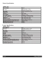
Page 18: ...z 1 Phase Dedicated 20 Amp circuit MODEL 5512E Circuit NEMA Electrical Drive Motor Compressor Cooling Weight Mix Hopper Capacity Freezing Cylinder Cap Refrigerant Refrigerant Charge High Side approximate operating pressure Low Side approximate operating pressure High Side Design Pressure Low Side Design Pressure See Serial Number Plate 1 5 gallons 5 7 liters per side 3 gallons 11 35 liters per sid...

Page 19: ...ct replace if necessary 2 Inspect replace if necessary 2 X Thick Product plunger 4 Standard Product plunger 6 X 4 or 6 Inspect replace if necessary Maximum 1 Inspect clean if necessary Maximum 1 Drive shaft Drive belts Scraper blades on dasher Square cut o ring on valve body face plate Front stator flange bearing Rear stator flange bearing Dispense valve o rings Carb tube o rings Cleaning brush Co...

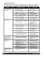
Page 20: ...ose of product Allow product to refreeze Frozen product too Consistency control set too firm Readjust consistency control stiff or freezer runs Dispensing valve not fully closed Close valve lubricate continuously properly Frozen product not Power switch OFF Turn Power Switch to ON dispensing Insufficient mix in storage hopper Refill storage hopper light on beeper Carburetor in off position Set car...

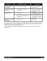
Page 21: ... or improperly sized Connect freezer directly to electrical wire power source using properly sized wiring Thumping sound from Worn drive belt Replace belt inside freezer PROBLEM PROBABLE CAUSE SOLUTION If you still need help call our service department at 800 695 4500 USA Canada only or 502 425 4776 Monday through Friday 8 am 8 pm EST or an authorized service center in your area Please have the mo...

Page 22: ...Page 22 Crathco 5512 Manual Exploded View Model 5512 Final Assembly Exploded View Model 5512 E Final Assembly ...

Page 23: ...2 W0211212 RH CENTER SHELF ANGLE 48 W0572298 ELECTRICAL BOX COVER 45 W0471134 SLEEVE STANDPIPE 37 W0480450 VALVE BODY 36 W0480445 VALVE HANDLE Item Part Number Description 35 W0211206 RH FRAME LEG 34 W0211205 LH FRAME LEG 33 W0471128 CARBORATOR ASSY 32 W0211225 FRONT PANEL 5512 29 W0451067 SLUSH DRIVE SHAFT 28 W0450209 BELTS 27 W0450053 SHEAVE 25 W0430028 STATOR WELDMENT 23 W0430024 BLIND FLANGE B...

Page 24: ...52 W0211212 RH CENTER SHELF ANGLE 48 W0572298 ELECTRICAL BOX COVER 45 W0471134 SLEEVE STANDPIPE 37 W0480450 VALVE BODY 36 W0480445 VALVE HANDLE Item Part Number Description 35 W0211206 RH FRAME LEG 34 W0211205 LH FRAME LEG 33 W0471128 CARBORATOR ASSY 32 W0211225 FRONT PANEL 5512 29 W0451067 SLUSH DRIVE SHAFT 28 W0450209 BELTS 27 W0450053 SHEAVE 25 W0430028 STATOR WELDMENT 23 W0430024 BLIND FLANGE ...

Page 25: ...X 1 CAP SCREW 17 W0610264 10 24 X 1 4 TRUSS HD 16 W0610110 8 X 3 8 PAN HD 15 W0451000 PULLEY 14 W0380009 FLANGE BEARING 13 W0321022 MOTOR ASSEMBLY Item Part Number Description 12 W0321013 MOTOR ADJ NUT 11 W0320221 FAN BLADE 10 W0320220 FAN MOTOR 9 W0211204 FRAME BOTTOM PLATE 8 W0210169 MOTOR CRADLE 7 W0201080 FAN SHROUD 6 W0200413 COMPRESSOR GROMMET 5 W0200412 COMPRESSOR SPACER 4 W0200411 FAN MOUN...

Page 26: ... X 1 CAP SCREW 17 W0610264 10 24 X 1 4 TRUSS HD 16 W0610110 8 X 3 8 PAN HD 15 W0451000 PULLEY 14 W0380009 FLANGE BEARING 13 W0321023 MOTOR ASSEMBLY Item Part Number Description 12 W0321013 MOTOR ADJ NUT 11 W0320221 FAN BLADE 10 W0320216 FAN MOTOR 9 W0211204 FRAME BOTTOM PLATE 8 W0210169 MOTOR CRADLE 7 W0201080 FAN SHROUD 6 W0200413 COMPRESSOR GROMMET 5 W0200412 COMPRESSOR SPACER 4 W0200411 FAN MOU...

Page 27: ...VE LINE 22 W0201406 L H SOLENOID LINE 21 W0650112 FILTER DRIER 20 W0201405 R H SOLENOID LINE 19 W0201404 BARREL SOLENOID LINE 18 W0201403 HOPPER SOLENOID LINE Item Part Number Description 17 W0620101 1 4 COUPLING 16 W0620110 1 4 ELBOW 15 W0620103 3 8 STRAIGHT COUPLE 14 W0201402 FILTER HOPPER SOLE LINE 13 W0201401 SOLENOID ELL S 12 W0200133 COMPRESSOR 11 W0200256 CONDENSER 9 W0620125 1 2 STRAIGHT C...

Page 28: ...LVE LINE 22 W0201406 L H SOLENOID LINE 21 W0650112 FILTER DRIER 20 W0201405 R H SOLENOID LINE 19 W0201404 BARREL SOLENOID LINE 18 W0201403 HOPPER SOLENOID LINE Item Part Number Description 17 W0620101 1 4 COUPLING 16 W0620110 1 4 ELBOW 15 W0620103 3 8 STRAIGHT COUPLE 14 W0201402 FILTER HOPPER SOLE LINE 13 W0201401 SOLENOID ELL S 12 W0200134 COMPRESSOR 11 W0200256 CONDENSER 9 W0620125 1 2 STRAIGHT ...

Page 29: ... Assembly S S PROBE W0572362 ACETAL DELRIN SLEEVE W0572361 ADD SILICON SEALANT TO BACK OF SLEEVE ONLY MACHINE SCREW W0610299 INTERNAL TOOTH LOCKWASHER W0611224 RING EYE TERMINAL FLAT WASHER W0611241 PLASTIC SPACER W0572360 HOLE IN REAR OF HOPPER PAN ...

Page 30: ...Page 30 Crathco 5512 Manual 1 2 Rough Side of Ceramic Smooth Shiny Side CRATHCO MACHINE ASSEMBLY CHECK LIST W0631230 ...

Page 31: ...7 SWITCHING RELAYS R3 R4 W0570655 CONTACTORS TR1 TR2 W0570873 TRANSFORMERSREQUIRE2 W0570205 SW2 SW3 W0570939 MODE SWITCHES SC W0570672 START CAPACITOR RC W0570673 RUN CAPACITOR Item Part Number Description SW1 SW4 W0570940 ON OFF SWITCH WITH 2 W1571507 FUSE HOLDERS CC W0570880 COMPRESSOR RELAY FU2 FU4 W0570823 3 2 AMP FUSE CB1 CB2 W0650910 CIRCUIT BOARDS FU1 FU3 W0570842 5 0 AMP FUSE WITH 2 W15715...

Page 32: ...677 SWITCHING RELAYS R3 R4 W0570655 CONTACTORS TR1 TR2 W0570873 TRANSFORMERSREQUIRE2 W0570205 SW2 SW3 W0570939 MODE SWITCHES SC W0570672 START CAPACITOR RC W0570673 RUN CAPACITOR Item Part Number Description SW1 SW4 W0570940 ON OFF SWITCH WITH 2 W1571507 FUSE HOLDERS CC W0570880 COMPRESSOR RELAY FU2 FU4 W0570823 3 2 AMP FUSE CB1 CB2 W0650913 CIRCUIT BOARDS FU1 FU3 W0570842 5 0 AMP FUSE WITH 2 W157...

Page 33: ...Crathco 5512 Manual Page 33 Model 5512 Electrical Components Front Electrical Box ...

Page 34: ...Page 34 Crathco 5512 Manual Model 5512 E Electrical Components Front Electrical Box ...

Page 35: ...S 11 W0610138 SCRW 8 32 X 1 4 RND HD SLT NOT SHOWN 12 W0572417 COMPRESSOR COMPONENT BUNDLE NOT SHOWN 13 W0572413 LEFT REAR HARNESS NOT SHOWN Item Part Number Description 1 W0572373 CONTACTOR BOX 2 W0570655 CONTACTORS 3 W0570880 COMPRESSOR RELAY 4 W0570673 RUN CAPACITOR 5 W0570672 START CAPACITOR 6 83106 RELAY 7 W0630802 CABLE TIE 7 375 NATURAL NOT SHOWN 8 W0610264 SCRW 10 24 X 1 4 TRUSS HD PH NOT ...

Page 36: ...ITCH BRACKET 23 W0572700 SERVE SWITCH BRACKET 22 W0570916 REED SWITCH NORMALLY OPEN 21 W0631630 LIGHTED ELECTRICAL BOX LENS 20 W0572357 ELECTRICAL BOX 19 W1631508 WIRE SADDLE 18 W0630804 WIRE TIE 17 W0630801 CABLE TIE 16 W0630008 HEYCO BUSHING 15 W0611037 6 32 HEX NUT ZINC PLATED Item Part Number Description 14 W0611038 8 32 X 1 4 ROUND HD SLOTTED 13 W0610131 8 32X1 4SELFTHREADINGPHILLIPS 12 W0610...

Page 37: ...Crathco 5512 Manual Page 37 Models 5512 5512 E Spinner Wire Hookup Models 5512 5512 E Compressor Contact Detail ...

Page 38: ...Page 38 Crathco 5512 Manual Model 5512 Ladder Diagram ...

Page 39: ...Crathco 5512 Manual Page 39 Model 5512 E Ladder Diagram ...

Page 40: ...QUIRE 1 EA W0570308 99 W0570677 SOLID STATE RELAYS 98 W0570659 TRANSFORMERS REQUIRE 2 W0570205 97 W0570939 MODE SWITCHES 96 W0570619 START CAPACITOR Item Part Number Description 95 W0570617 RUN CAPACITOR 94 W0570618 COMPRESSOR RELAY 93 W0570940 ON OFF SWITCH 92 W0570823 3 2 AMP FUSE 91 W0570217 TERMINAL CONNECTORS ORANGE 90 W0650910 CIRCUIT BOARD 89 W0570842 5 0 AMP FUSE 88 W0570047 BALLASTS 87 W0...

Page 41: ...EQUIRE 1 EA W0570308 99 W0570677 SOLID STATE RELAYS 98 W0570873 TRANSFORMERS REQUIRE 2 W0570205 97 W0570939 MODE SWITCHES 96 W0570672 START CAPACITOR Item Part Number Description 95 W0570673 RUN CAPACITOR 94 W0570880 COMPRESSOR RELAY 93 W0570940 ON OFF SWITCH 92 W0570823 3 2 AMP FUSE 91 W0570214 TERMINAL CONNECTORS ORANGE 90 W0650913 CIRCUIT BOARDS 89 W0570842 5 0 AMP FUSE 88 W0570053 BALLASTS 87 ...

Page 42: ...Page 42 Crathco 5512 Manual Models 5512 5512 E Refrigeration Schematic ...

Page 43: ......

Page 44: ...ms Espressimo Espresso Machines Crathco Hot Beverage Dispensers Crathco Cold and Frozen Beverage Dispensers AMW Coffee and Tea Systems Tel 502 425 4776 Fax 502 425 4664 1 800 695 4500 P O Box 35020 Louisville KY 40232 USA www grindmaster com email info grindmaster com ...

Reviews: