background image

Grindmaster Corporation 

4003 Collins Lane
Louisville, KY 40245 
(502) 425-4776     (800) 695-4500
(800) 568-5715 (Technical Service Only)
FAX (502) 425-4664
www.grindmaster.com

1103 Form #AM-352-04
Part # A090-094
ECN # 1091
Rev. Rel.

© Grindmaster Corporation, 1998
PRINTED IN THE USA

American Metal Ware

®

Brewers

Operation and Instruction Manual

for

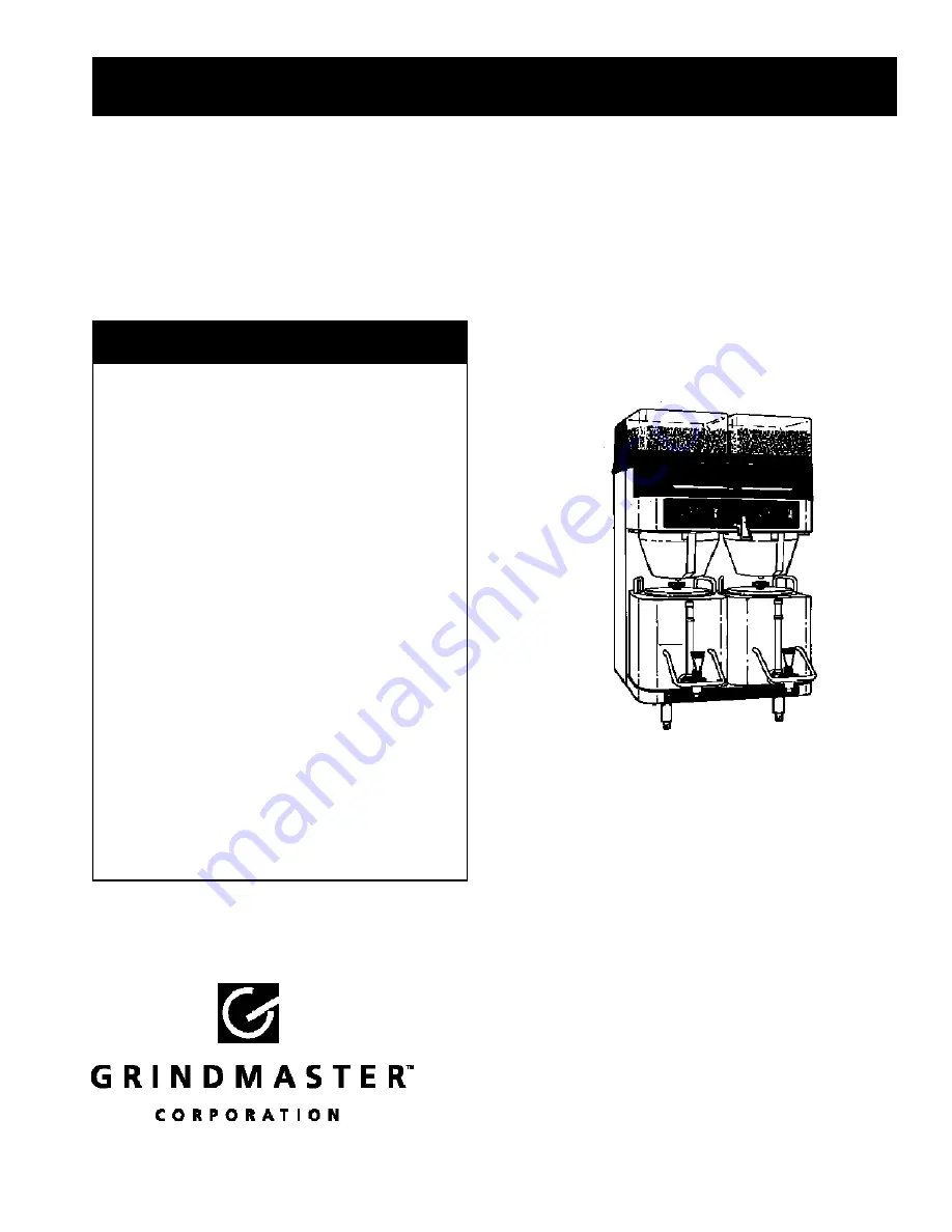
Model: P400GNB-E   

Prior authorization must be obtained 
from Grindmaster Corporation
for all warranty claims.

Model P400GNB-E

TABLE OF CONTENTS

Warning Labels ........................................2

Start Up Procedures .............................3-6

Operation ..............................................6-7

Adjustments ..........................................7-9

Care and Cleaning............................10-12

Service ..............................................12-13

Troubleshooting ................................14-18

Installation Rough-In Drawings ..............19

Exploded Views ................................20-25

Wiring Diagrams ...............................26-27

Summary of Contents for American Metal Ware P400GNB-E

Page 1: ...THE USA American Metal Ware Brewers Operation and Instruction Manual for Model P400GNB E Prior authorization must be obtained from Grindmaster Corporation for all warranty claims Model P400GNB E TABLE OF CONTENTS Warning Labels 2 Start Up Procedures 3 6 Operation 6 7 Adjustments 7 9 Care and Cleaning 10 12 Service 12 13 Troubleshooting 14 18 Installation Rough In Drawings 19 Exploded Views 20 25 W...

Page 2: ...HAZARD COFFEE BASKET CONTAINS VERY HOT LIQUID UNTIL THE DRIP THROUGH IS COM PLETED EARLY REMOVAL OF THE BASKET COULD RESULT IN BURNS WARNING ELECTRIC SHOCK HAZARD NEVER USE THE GROUND CONDUCTOR AS A NEUTRAL THIS COULD CAUSE ELECTROCUTION WARNING ELECTRIC SHOCK HAZARD DANGEROUS ELECTRIC VOLTAGES ARE PRESENT NEAR ADJUSTABLE COMPO NENTS ONLY QUALIFIED SERVICE PERSONNEL SHOULD MAKE ADJUSTMENTS WARNING...

Page 3: ... lime chlorine or iron content Contact our Technical Service department to select the filter for your water conditions Electrical Hook up 1 The electric ratings for your brewer are printed on its nameplate The electrical rating is one of the following 120 208 240 Volt 1 Phase 4 supply wires standard configuration 208 240 Volt 1 Phase 3 supply wires no neutral line 120 208 240 Volt 3 Phase 5 supply...

Page 4: ...ed Stop switch A water faucet and a red Water Hot light are located between the 2 sets of touchpad controls Touchpad Functions Refer to Figure A Each touchpad has 3 switch pads with symbols above each switch pad that illuminate the selected operation The 1st switch left position is used to select the PORTION SIZE desired 1 2 gal 1 gal and 1 1 2 gal Default setting is 1 1 2 gal Pressing the button ...

Page 5: ... not desired To disable this feature the touchpad assemblies need to be replaced Contact our Technical Service Department Low Temp No Brew This feature prevents the operator from brewing coffee before the desired water temperature has been reached This feature is standard on the unit but may be disabled if not desired Temperature and Timing Controls Refer to Figure B Temperature and the various pr...

Page 6: ...e Adjustment Knob Temperature adjustment is accomplished by rotating the small knob to the left of the brewer selector switch Clockwise rotation will increase the temperature setpoint while counter clockwise rotation will decrease the setpoint Operation 1 Place an empty warm shuttle under the sprayhead Turn on the warmer 2 If the shuttle is not warm allow the warmer to heat the shuttle A short bre...

Page 7: ... is achieved Refer to Temperature and Timing Controls section for more information on controls Before adjusting throw weight grind a batch of coffee and measure the coffee weight Record this value To adjust throw weight 1 Remove the controller access panel 2 Slide the brewer selector switch to the appropriate position 3 Press the Select button momentarily a LED will light up to indicate which timi...

Page 8: ...olume Adjustment Brew volume is adjusted by adjusting the timer values of the controller refer to Temperature and Timing Controls section Before adjusting brew timing brew a batch of water and measure the brew volume Record this value To adjust brew timing 1 Remove the controller access panel 2 Slide the brewer selector switch to the appropriate position 3 Press the Select button momentarily a LED...

Page 9: ...ght and in front of the brew tee 3 Open the valve by turning the valve handle counter clockwise to the desired setting Refer to the information below Bypass Setting Bypass Of Total Brew Closed 0 1 revolution 8 2 revolutions 12 3 revolutions 22 4 revolutions 33 4 Measure the bypass setting a Remove the brew basket b Place an empty shuttle with lid removed under the sprayhead c Place a measuring cup...

Page 10: ...st the stops on the brush Be sure to remove all the residue from the grinder outlet chute both above and below the shutter door Remove the brush and release the finger tab on the shutter door 5 Once the spray dome and grinder outlet chute are clean the spray head assembly may be reinstalled onto the spray tee outlet nut Hold the tab forward on the spray head until it hits the stop Place the spray ...

Page 11: ...that are in contact with food must be washed with warm soapy water rinsed sanitized and air dried NOTE The person cleaning the parts should do so with clean hands 6 Reassemble hopper cradle assembly in reverse order of disassembly Removal of Grinder Assembly Both Stations 1 Remove the hopper cradle assembly as described above 2 Remove motor base mounting bolt from unit one per motor assembly 3 Dis...

Page 12: ...nk 1 Disconnect power and remove the hopper cradle assembly as described above 2 Disconnect the wire leads to the water heating elements thermistor thermodisc and water probe Note the positions of each wire going to the heaters and the other components 3 Remove the tank cover by removing the 3 retaining wing nuts and lifting the cover 4 De lime the water tank using a commercial grade urn cleaner F...

Page 13: ...ct the wires attached to the valve 4 Follow the To Drain Water Tank procedure on page 12 to drain the water tank below the brew valve s water level 5 Tilt the inlet of the valve downward and pull sideways to disconnect the valve from the spray tee Disconnect the tubing from the valve To Remove and Replace the Heaters 1 Turn off power to the brewer 2 Remove the hopper cradle assembly as described i...

Page 14: ...er grind Check sprayhead temperature should be greater than 185o F Adjust brew time at the controller Spray deflector broken or missing Readjust coffee portion Coarsen grind setting Use proper filter Use no more than 9 oz of coffee Coarsen grind You must dump old coffee and use fresh new filter for each brew Clean sanitize de lime Install a water filtration system Adjust timer to desired value or ...

Page 15: ...with 120 Vac If valve is energized and not opened replace part Check and replace fuse if blown Visually inspect valve Clean lime from valve Seat cup or entire valve may need replacement Reduce the water tank temperature Adjustment knob is located on the control board face BREWING PROBLEMS Problem Hot light flashing slow rate and ER1 code dis played on control board Also unit will not heat water pe...

Page 16: ...LEMS Problem No light illuminated on unit No light illuminated on either touchpad No light illuminated on one touchpad Water is hot but Water Hot light not illuminated Possible Causes No power to the unit No power to the unit Touchpads not connected to control board Bad low voltage transformer Bad control board Touchpad not connected to control board Polarity of light connected reversed Part defec...

Page 17: ...e heater relay thermodisc and contactor Contactor coil faulty Heater relay faulty Fuse blown on control board Solutions Water fill valve has been open for more than 5 minutes This causes error code ER1 to occur and shut down the tank heaters Restore water to the unit and reset unit Reset thermodisc Review unit to confirm no damage occurred due to overheating of water tank Reset thermodisc If therm...

Page 18: ...tween terminals and or tank body replace parts Check contacts of contactor If corroded or faulty replace part Check resistance across element with power conductors disconnected If resis tance is much less than 8 Ohms or much more than 15 Ohms replace part Replace touchpad assemblies with assemblies without that option if desired HEATING PROBLEMS If you still need help call our Service Department a...

Page 19: ...HOLES F OR OPTIONAL REAR ACCESS FOR UTILITY CONNECTIONS 4 1 211 18 11 4 1 4 1 1 4 DIA ACCESS HOLE FOR t o t r WATER CONNECTION 0 0 9 19 1 8 FRONT VIEW CONNECTION MADE TO 3 8 MALE FLARE 1 1 4 D c s HO rnR ELECTRICAL CONNECTION 22 6 3 811 c 23 SIPE VIEW STD UTILITY ACCESS LOCATION 49 3 4 ALTERNATE UTILITY ACCESS LOCATION ...

Page 20: ... I J _ 1 1 1 DESCRIPTION nll u w V V Y lAUn II m R IIO I n_ DI llr SEE lll PEB QRAQQLE A ENBOC FOR EXPLODED VIEW SEE QBINPINQ SSfHBLX FOR EXPLODED VIEW SEE QIQITN GA JI BQ4RO ASSEMBLY FOR EXPLODED VIEW SEE CONJRQL PANEL 6S ENBLV FOR EXPLODED VIEW EE BRE nNG ASSEMBLr FOR EXPLODED VIEW ...

Page 21: ...Page 21 American Metal Ware P400GNB E Exploded View P400GNB E Brewing Assembly ...

Page 22: ...American Metal Ware P400GNB E Page 22 Exploded View P400GNB E Electric Controls P400GNS E 208 230 VAC SINGLE PHASE P400GNB E II 208 230 VAC 3 PHASE WITI l NO NEUTRAL DWG P400GNB 121 REVISION A ...

Page 23: ...K Pl ATE S EA 11 A551 lRIVE CA A552 020 SPHl111tl A 51 067 _ _ ___ NA A 1 1 1 lENSION IINr A 51 1 180 1 s 1 1 I EARING 16 A ltil I I i GF ND r NR 17 A533 M IK 1 5 VAr 1 2 HP rn I Tl A533 042 Ut 7 1 yµ 1 12 11 I RAI 18 A550 223 HARNESS MOJlllil 115V Il I A 55CJ 224 HARNESS MOTOR 231 N tN Ni 1 19 A Ml 112 N JT 1 4 20 TlNNERUill 20 U1L n _R Ill l IUrNT li n1lllil uni INT 1 A801ff IM 9 II T 1 4 2 l x ...

Page 24: ...ss ASSEMBLY TOUCH PAD 11 A546 250 DECAL COLUMBIA SERIES 12 A417 172 WELDMENT CONTROL PANEL 13 AS 46 251 DECAL COLUMBIA CONTROL PANEL 14 AP400 346 COLUMBIA WIRE BASKET 15 ABB1 5SS SS BREW BASKET DWG P400GN8 116 REVISION C 15 SHUTTER ASSEMB Y BREAKDOWN ITEM 1 a 1b le 1d le 1f 1 1t PART NO DESCRIPTION 3 b g tfo u il8 Hb v A551 078 SPRING PIN lf8 x1 2 SS A554 122 SOLENOm 240 VAc A551 077 SPRING o 100 ...

Page 25: ...Page 25 American Metal Ware P400GNB E Other Exploded Views Digital Control Board Assembly Warmer Shelf Assembly Hopper Cradle Assembly 7 ITEM ...

Page 26: ...American Metal Ware P400GNB E Page 26 Wiring Diagram P400GNB 208 230VAC Single Three Phase Wiring ...

Page 27: ...Page 27 American Metal Ware P400GNB E Wiring Diagram P400GNB 208 230VAC single three phase wiring with no neutral option I i i ...

Page 28: ......

Reviews: