SINEWAVE GRINFINEON CONTROLLER MANUAL
Rev 2.1
-15-
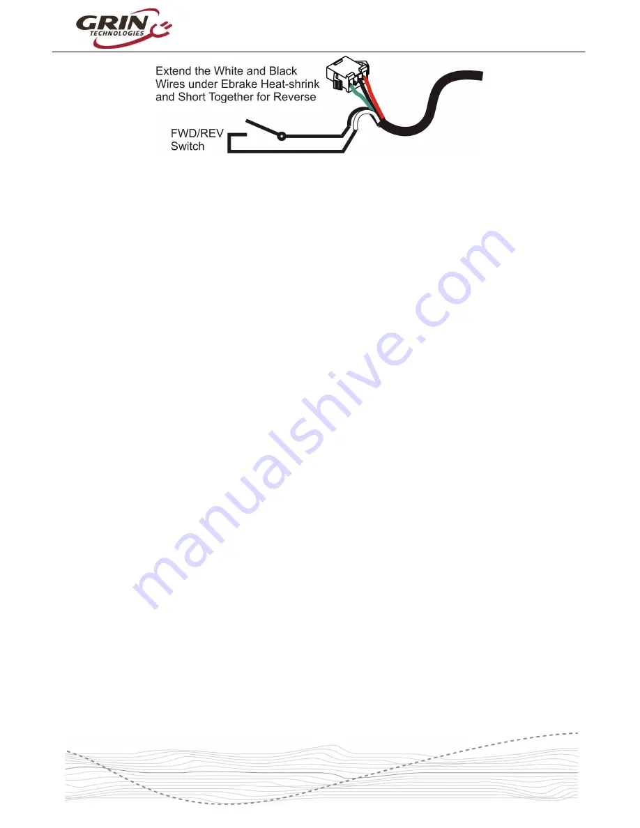
Figure 15: FWD/REV, Remove heatshrink tubing over ebrake connector to expose
spare white and black signal wires, and extend those to your reverse switch.
3.7
Fault Tolerant Hall
Normally a sensored motor/controller setup is somewhat vulnerable to damage of
the hall sensor itself, the hall wires, or the hall connector pins. If this happens, the
motor will run very rough or not at all. On the Sinewave Grinfineon controllers,
the control logic will still be able to operate in sensored sine wave mode even if
one of the hall sensors is damaged as it can interpolate the missing signal.
However, the initial starting can be a bit rough, and the ebrake input no longer
does regenerative braking but just does a controller cutoff.
4
Limitations
Although we tried to make this controller fairly universal, there are also more than
a few limitations that can affect its use in some applications.
4.1
eRPM Sensorless & Sensored
The maximum commutation frequency in sensorless mode is about 28000
eRPM. This is substantially higher than previous Grinfineon controllers (13000
eRPM) and will work with most geared hub motors just fine at typical ebike
speeds, but may still be limiting in very fast setups.
The electrical RPM is easy to calculate by taking the mechanical RPM of the
motor, multiplying it by the number of magnetic pole pairs in rotor, and then again
by the gear ratio if it is a geared hub.
For instance, Figure 16 is a diagram of a direct drive motor with 40 magnets.
That means there are 20 magnetic pole
pairs
. A 28000 eRPM would correspond
to a 1400 maximum mechanical RPM at the wheel, which is much faster than
you would have on a bicycle (200-400 rpm is more common); therefore this hub
would have no problem running sensorless at bicycle speeds.


