SINEWAVE GRINFINEON CONTROLLER MANUAL
Rev 2.1
-10-
Of the 36 possible ways to map the hall and phase wires, only 3 will spin the
motor properly in the forwards direction. Another 3 combinations will spin the
motor in reverse, and the remaining 30 combinations will either not turn the motor
at all, or will turn it with great inefficiency.
We recommend using a systematic approach to determine the hall and phase
mapping. First, plug together the hall wires in any pinout that you like. Then
connect the 3 phase wires together and test the motor. If it spins smoothly with
low current draw, then great. If not, then separate the Anderson phase plugs
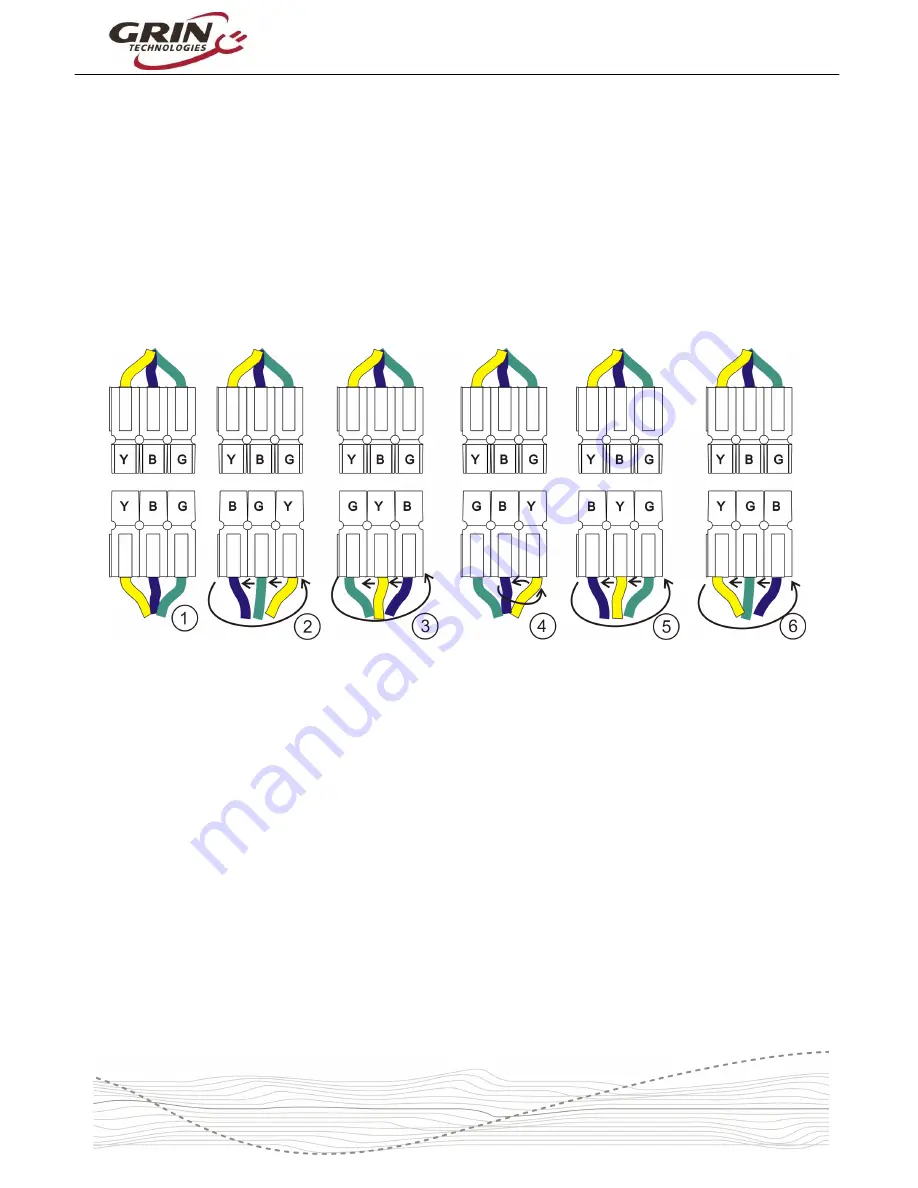
(they dovetail slide into each other) and keep cycling through the 6 possible
alignments testing each one. An easy way to keep track of this is by first ‘rotating’
the phase connectors through the first 3 positions as shown below.
Figure 9: Systematic Approach to Phase Pinout Mapping
Then swap any pair of plugs (yellow and blue swapped in above example), and
rotate through the 3 positions again. This will cover all 6 possible phase pinouts,
and one of those 6 should allow the motor to run smoothly.
If that one position spins the motor backwards, then you can swap a pair of the
hall sensor wires, repeat the test to find the correct phase pinout and it will spin
the forwards direction.
Be aware that there are some incorrect hall/phase pinouts which will still spin the
motor when you apply throttle, but the motor will turn with great inefficiency and
draw higher than normal current, usually with a small ‘kick’ when the throttle is
first applied. You do not want to run the motor under load in this condition.
When the motor is running in sensored mode, the LED will be on steady without
blinking unless there is a fault error. In sensorless mode, the LED will flash at a
slow ~1 Hz rate.


