background image

10

8.

6.

7.

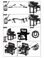
Attach the Door Bracket to the low holes in the
front legs with the end tabs pointing upward and
flange to the rear, pointing downward. Use 2 of
1/4" x 1/2" Phillips Head Screws. Do not fully
tighten. See

Figure 4

.

Attach the Door Stop to the bottom shelf, with
t h e f l an g e f ac i n g t h e f r o n t , u s i n g 2 o f
3/16" x 3/8" Phillips Head Screws. Fully tighten.
See

Figure 4

.

Place doors into the hinge holes of the bottom shelf
and Door Bracket. Push Door Bracket down until
doors are secure and can open and close freely.
Do not full tighten Door Bracket screws. See

Figure 4

.

Remove protective film from Doors. Install Door
Handle to Doors using 4 of 3/16" x 1/4" Phillips Head
Screws. See

Figure 4.

Attach lighting stick to the Right Rear Leg, below
side shelf bracket using 1 M4 x 10 self-tapping
screw.

Attach the 2 Bowl Brackets to Bowl Side Panel
using 4 of 1/4" x 1/2" Phillip Head Screw, 1/4" Nuts
and 1/4" Washers. Fully tighten. See

Figure 5

.

9.

10.

1/4" x 1/2" Phillips Head Screw x 2

1/4" x 1/2" Phillips Head Screw x 4

3/16" x 3/8" Phillips Head Screw x 2

Figure 4

Figure 5

DOOR

HANDLE

DOOR BRACKET

DOOR PLATE

3/16" x 1/4"

Phillips Head Screw x 4
(found in door handle)

DOOR STOP

LIGHTING

STICK

M4 x 10 Self-Tapping Screw x 1

BOWL PANEL

BOWL BRACKET

1/4" Lock Nut x 4

BOWL SIDE PANEL

BOWL BRACKET

11.

1/4" W asher x 4

Summary of Contents for SS54 LP

Page 1: ...sembled Failure to follow these instructions could result in serious bodily injury and or property damage This grill is intended for outdoor use only and is not intended to be installed in or on recre...

Page 2: ...afety Instructions Grill Installation Codes The installation must conform with local codes or in the absence of local codes with either the National Fuel Gas Code ANSI Z223 1 NFPA 54 or CAN CGA B149 1...

Page 3: ...ication with the vapor space of the tank The tank supply system must be arranged for vapor withdrawal The LP gas tank used must have a collar to protect the tank valve 1 2 3 The Regulator and Hose ass...

Page 4: ...for damage as you proceed Do not operate your grill if it appears damage If you have ques tions during the assembly process call 8 00am 5 00pm EST Monday through Friday 1 800 667 7313 Remove white PV...

Page 5: ...1 4 x 1 2 Phillips Head Screw M4 x 10 Self Tapping Screw 3 16 x 3 8 Phillips Head Screw 3 16 Nut Side Burner Control Knob Spring Side Burner Control Knob Seat Lighting Stick Customized Wrench Hose Hol...

Page 6: ...all us 8 00am 5 00 pm EST Monday through Friday at 1 800 667 7313 1 4 x 2 1 2 Phillips Head Screw QTY 12 1 4 x 1 2 Phillips Head Screw QTY 30 1 4 Lock Nut QTY 16 Manual Lighting Stick QTY 1 AA Battery...

Page 7: ...reach Turn carton upside down and it will provide a comfortable height work surface for grill assembly 7 1 2 4 3 5 6 7 8 9 45 10 12 13 14 11 16 17 15 20 19 27 46 44 25 49 22 23 24 30 36 28 1 28 32 34...

Page 8: ...Bowl Panel Front Lid Hinge Bowl Bracket Electric Wire Set Gas Valve Manifold Assembly Gas Fitting Control Panel Control Knob Seat Spring Control Knob Ignitor 4 port Battery Grease Tray Side Shelf Brac...

Page 9: ...correctly assembled Remaining components cannot be assembled if leg postions are incorrect Install the four cart legs to the indicated corners of the bottom shelf using 8 of the 1 4 x 2 1 2 Phillips H...

Page 10: ...crews See Figure 4 Remove protective film from Doors Install Door Handle to Doors using 4 of 3 16 x 1 4 Phillips Head Screws See Figure 4 Attach lighting stick to the Right Rear Leg below side shelf b...

Page 11: ...8 of 1 4 x 1 2 Phillips Head Screws See Figure 8 Place the Side Shelves over the Side Shelf brackets Secure firmly using 4 of 1 4 x 1 2 Phillips Head Screws and 1 4 Lock Nuts See Figure 8 Align the Si...

Page 12: ...opening above Cart Side Panel Press the hose of the LPG Regulator into the Hose Holder above Cart Side Panel Secure firmly using 2 of 3 16 x 3 8 Phillips Head Screw and 3 16 Nut See Figure 13 3 16 x...

Page 13: ...Gas Collector Box until the gap is correct Return the Gas Collector Box to its original horizontal position secure the inside Nut and try the Electrode Check again 5 If no clicking sound is heard chec...

Page 14: ...r ANSI Z21 58a 2002 2 Inspect the Valve Connection Port and Regulator assembly Look for damage or debris Remove any debris Inspect Hose for damage Never use damaged or plugged equipment 3 Hang your fi...

Page 15: ...k that the end of each Burner Tube is properly located over each valve orifice Make sure all gas connections are securely tightened Open the Grill Lid 1 2 3 4 WARNING Shut off gas supply to the gas gr...

Page 16: ...acket please call the Customer Service Dept at 1 800 667 7313 Turn gas off at source and turn the Control Knobs to OFF Wait at least five minutes for gas to clear then retry Check gas supply and conne...

Page 17: ...gas collector box The edge of the collector box should be overlapping the Burner Port Replace Flame Tamers and the Cooking Grids Reconnect the gas source and observe the Burner flame for correct oper...

Page 18: ...rner and out the ports Cleaning The Burner Tubes and Burner Ports To reduce the chance of FLASH BACK you must clean the Burner Tubes at least once a month in late summer or early fall when spiders are...

Page 19: ...with a fiber type brush and turn over to allow the burner heat to burn off any stuborn food residue The Ceramic Flame Tamers work equally well on either side Grease Tray Receptacle and Heat Shield To...

Page 20: ...Deep frying and smoking are also best cooked in this manner because they require direct heat Your grill will get very hot Never lean over the cooking area while using your grill Do not touch cooking s...

Page 21: ...Warranty Registration Card immediately This limited warranty does not apply to any damage due to transportation installation purchaser servicing accident abuse fire alteration of the product in any w...

Reviews: