


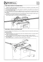

4. DESCRIPTION OF THE MACHINE
Our Boring Machines have been manufactured to make a series of holes at a fixed 32-mm distance be-
tween centres on wooden pieces (with maximum precision).
The head has its fulcrum on the machine table and it can be tilted until a 90-degree angle. The pieces to
be bored are fed by the operator, who places them on the machine table. The operator will carry out the
required adjustments by pressing the control pedal before locking the pieces into place with the relevant
hold down clamps and starting boring operations.
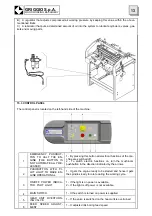
The following parts make up the machine:
•
A steel frame structure
•
Spindlehead unit with transmission and drill spindles with quick-change seat (standard).
•
Hold down clamps unit to clamp the piece to be cut in a vertical position.
•
Pneumatic system for head positioning and head feed.
•
Back stops so as to obtain the same vertical and horizontal boring distance
•
Crank mechanism to adjust spindles height, equipped with mechanical counter and quick-depth de-
vice to adjust hole depth from 0 mm to 100 mm.
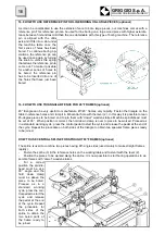
4.1 APPLICABLE TOOLS
Quick-change spindle drills with a 10mm-diameter shank L=20mm.
Drills up to 40mm-diametre outside the rack can be used; 100 mm maximum working length (attachment
is not taken into account).
REMOVING OR TAMPERING WITH SAFETY DEVICES MAY CAUSE SERIOUS ACCIDENTS. IT IS
FORBIDDEN TO REMOVE, EXCLUDE OR MODIFY SUCH DEVICES. PERIODICAL CHECKS
MUST BE CARRRIED OUT TO MAKE SURE THAT SAFETY DEVICES ARE ALWAYS IN GOOD
WORKING ORDER. ANY DEFECT OR POSSIBLE PROBLEM IS TO BE DEALT WITH IMMEDI-
ATELY.
3. OPERATIVE NOTES
1) To operate the machine safely and correctly, follow the indications contained in this manual care
fully and scrupulously.
2) The machine will have to be operated only by personnel who is both qualified and over 18. People
responsible for safety should make sure that the machine operator has read and fully understood all the
information contained in this manual.
3) Maintenance interventions must be carried out only by personnel who is both qualified and of age.
4) Personnel responsible for periodical and extraordinary servicing must have a good knowledge of
mechanics and electronics.
5) Keep away from any moving part in the machine.
Never touch the spindles and /or the drills when the machine is operational.
6) Never superimpose wood pieces to be worked. Always bore one piece at a time, after having ad-
justed the machine correctly.
WOODWORKING MACHINES CAN BE DANGEROUS
5
GRIGGIO S.p.A.
WOODWORKING MACHINERY
Summary of Contents for GF 21
Page 2: ......
Page 4: ......
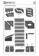
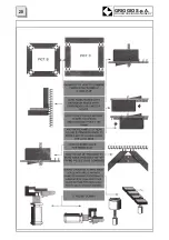
Page 23: ...16 10 WOODWORKING EXAMPLES 19 GRIGGIO S p A WOODWORKING MACHINERY ...
Page 24: ...GRIGGIO S p A WOODWORKING MACHINERY 20 ...
Page 33: ...29 GRIGGIO S p A WOODWORKING MACHINERY 26 SPARE PARTS CATALOGUE ...
Page 35: ...TABLE 1 FRAME 31 GRIGGIO S p A WOODWORKING MACHINERY ...
Page 37: ...TABLE 2 MACHINE TABLE 33 GRIGGIO S p A WOODWORKING MACHINERY ...
Page 39: ...TABLE 3 RACK 35 GRIGGIO S p A WOODWORKING MACHINERY ...
Page 41: ...TABLE 4 LIMITERS 37 GRIGGIO S p A WOODWORKING MACHINERY ...
Page 43: ...TABLE 5 SPINDLES UNIT 39 GRIGGIO S p A WOODWORKING MACHINERY ...
Page 45: ...TABLE 6 HOLD DOWN CLAMPS FRAME 41 GRIGGIO S p A WOODWORKING MACHINERY ...
Page 47: ...TABLE 7 BACK STOP 43 GRIGGIO S p A WOODWORKING MACHINERY ...
Page 49: ...TABLE 8 HOLD DOWN CLAMPS 45 GRIGGIO S p A WOODWORKING MACHINERY ...
Page 51: ...TABLE 9 SPINDLEHEAD 47 GRIGGIO S p A WOODWORKING MACHINERY ...
Page 53: ...TABLE 10 EXTENSION FENCE 49 GRIGGIO S p A WOODWORKING MACHINERY ...
Page 55: ......


