


Telephonics Corporation
R
A D A R
S
Y S T E M S
D
I V I S I O N
TM113806 (3/10)
2-1/2-2 blank
SECTION 2
2. INSTALLATION
2.1 GENERAL
This section contains information for the installation of the RDR-1700A Radar System. Included in
this section are equipment outline drawings, installation pictorials, and an electrical interconnect
diagram of the system configuration. These drawings should be reviewed by the installing agency and
requirements peculiar to a particular airframe established before installation is begun.
NOTE:
The conditions and tests required for TSO approval of this article are
minimum performance standards. It is the responsibility of those desiring to
install this article either on or within a specific type or class of aircraft to
determine that the aircraft installation conditions are within TSO standards.
The article may be installed only if further evaluation by the applicant
documents an acceptable installation and is approved by the Administrator.
2.2 UNPACKING
Use care when unpacking the RDR-1700A Radar System components. Open shipping cartons and
carefully remove all items. Check the contents to ensure that all items ordered have been included.
Visually inspect all units for any possible damage that may have occurred during shipment, such as
dents, deep abrasions, chipped paint, cracked glass, etc. If any equipment has been damaged in transit,
report the extent of damage to the transportation carrier immediately.
2.3 PRE-INSTALLATION
CHECK
Bench test the equipment to ensure that it is operable before installation. Bench test procedures are
given in Section 3 of this manual. A continuity and insulation test should be made on all cables and
wiring harnesses fabricated by the installing agency.
2.4 INSTALLATION
PLANNING
2.4.1
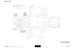
Outline and Inter-wiring Drawings
Outline drawings of the units that comprise the RDR-1700A system and the inter-wiring diagram are
located at the end of Section 2 of this manual (refer to Figure 2.4.1-1 through Figure 2.4.1-10).
The installer must fabricate cable assemblies. Mating connectors are supplied in an optional Install Kit
as shown in Section 1.3.1. The complete inter-wiring diagram is shown in Figure 2.4.1-11.
The document reference is online, please check the correspondence between the online documentation and the printed version.