


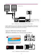

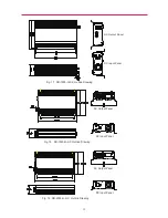


Fig. 13 SR-1000-G-X-X Layout
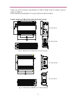
SR-500-G-X-X and SR-600-G-X-X have the same layout, please see the
SR-1000-G-X-X layout, please see the Fig. 13
Fig. 12 SR-500-G-X-X, SR-600-G-X-X Layout
21
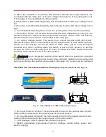
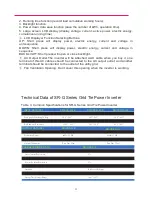
①.
DC Input Positive Terminal. This terminal will connect to the positive wire of solar
cables that connected with the positive pole of the solar panels.
②.
DC Input Negative Terminal. This terminal will connect to the negative wire of solar
cables that connected with the negative pole of the solar panels.
③.
Power Level LED. The three green LED indicators will start to cycle from left to right
when the grid and DC supply is detected. This indicates the inverter is operating under
normal condition. The rate of the cycle flashing is according to how much output power
is being fed to the utility grid . The more big output power is, the more fast the rate is.
④.
Fault LED. This red LED will indicate several informations:
DC Input Panel
AC Output Panel
⑥
Fig. 12
①②
③
④
⑤
AC Output Panel
⑥
⑤.
⑥.
⑦.
DC Input Panel
①②
③
④
⑤


