05.2012
38
2
b
1
c
5
4
3
1
A-D
Tetra
Subject to technical modifications
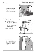
Fig. 38;
Couple the bottom link
(illustration with
ball bush with clamp/type guide cone)
►
Couple the bottom links (
1
) to the
implement's three-point axis (
2
) and lock.
During coupling, make sure that the
lock (
b
) engages securely.
►
Properly secure the coupling device.
Coupling the implement
7.2 Coupling the top link
NOTE
Attach the upper link (3) such
that it rises slightly relative to the
implement or is parallel to the
lower links (1) when in working
position.
This assures an almost parallel
implement behaviour.
The incline can be changed by inserting the
top link stock in position A to D.
Fig. 39; Top link position
Fig. 40; Insert top link stock
►
Insert the top link stock (4) in the
selected hole (fig.31, A to D).
►
Insert the anti-twist device of the top
link stock (c) into the opposite hole.
►
Secure the top link stock with the
locking pin (5).
Summary of Contents for Tetra 3001 L
Page 4: ...05 2012 4 Tetra Subject to technical modifications ...
Page 104: ......
Page 106: ......
Page 107: ...107 05 2012 Tetra Subject to technical modifications 21 0 EU Declaration of Conformity ...
Page 108: ......
Page 110: ......
Page 111: ......

