background image


NOTE

When correctly installed, the teeth on the depth stop rod
must be aligned with the teeth indicator on the depth stop
rod clamp.

8.5

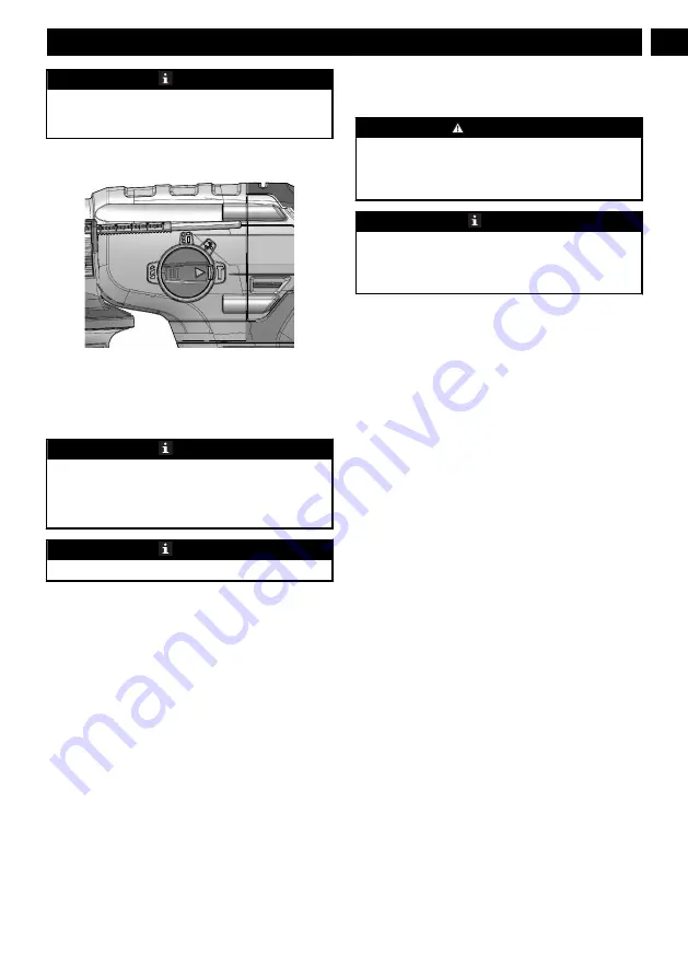
SELECT THE MODE

To change the operation mode, push the release button and
turn the mode selection switch to the correct position until it
clicks.

The machine is used for four functions: dri

ll

, hammer,

hammer drill, chisel, vari-lock and rotation stop


NOTE

Hammer drilling mode can destroy the structure of the
machine when used for fastening or drilling without SDS
Plus bits.

Use bits only with hard metal and SDS Plus shaft only.


NOTE

When hammer drilling, do not apply too much pressure.

8.6

DRILL

1. Examine the direction of rotation selector for the correct

setting (forward or reverse).

2. Attach the material to be drilled in a vise or with clamps

to keep it from turning.

3. Hold the drill tightly and put the bit at the correct

position.

4. Push the trigger to start the drill.
5. Move the drill bit into the workpiece and apply only

sufficient pressure to keep the bit cutting. Do not force
the drill or apply side pressure to elongate a hole.

6. When drilling on hard or smooth surfaces, use a center

punch to identify the necessary hole location. This can
prevent the drill bit from moving from the center.

7. When drilling metals, use a light oil on the drill bit to

keep it from overheating. The oil can prolong the life of
the bit and increase the drilling action.

8. If the bit jams in the workpiece or if the drill stalls, stop

the machine immediately. Remove the bit from the
workpiece and determine the reason for jamming.


WARNING

Drills have a tendency to grab and kick opposite to the
direction of rotation and could cause loss of control when
breaking through material. If not prepared, this loss of
control can result in possible serious injury.


NOTE

This drill has an electric brake. Release the trigger to stop
the chuck from turning. When the brake is working
correctly, sparks can be seen through the exhaust slots on
the housing. This is normal and is the action of the brake.

8.7

DRILL MATERIALS

WOOD DRILLING

For maximum performance, use high speed steel bits for
wood drilling.
1. Operate the machine at a very low speed to prevent the

bit from slipping off the starting point. Increase the speed
as the drill bit bites into the material.

2. When drilling through holes, put a piece of wood behind

the workpiece to prevent ragged or splintered edges on
the rear side of the hole.

METAL DRILLING

For maximum performance, use high speed steel bits for
metal or steel drilling.

1. Operate the machine at a very low speed to prevent the

bit from slipping off the starting point.

2. Hold a speed and pressure which let cut without

overheating the bit. Apply too much pressure can:
Overheat the drill; Wear the bearings; Bend or burn bits;
and Produce off-center or irregular-shaped holes.

3. When drilling large holes in metal, start with a small bit,

then complete with a large bit. Also, lubricate the bit with
oil to improve drilling action and increase bit life.

MASONRY DRLLING

For maximum performance, use carbide-tipped masonry
impact bits when drilling holes in brick, tile, concrete, etc..

1. Move adjustment button on hammer drill left for hammer

mode.

2. Apply light pressure and medium speed for best results in

brick.

3. When drilling holes in tile, practice on a scrap piece to

find the best speed and pressure. Operate the machine at a
very low speed to prevent the bit from slipping off the
starting point.

9

English

EN

Summary of Contents for HM24L00

Page 1: ...20 04 18 GW 24V Rotary hammer 3803502AZ B HMD401 EN OPERATOR MANUAL FR MANUEL D OP RATEUR SDS ROTARY HAMMER MARTEAU PERFORATEUR SDS ES MANUAL DEL OPERADOR MARTILLO GIRATORIO SDS HM24L00 www greenworks...

Page 2: ...D401 EN OPERATOR MANUAL FR MANUEL D OP RATEUR SDS ROTARY HAMMER MARTEAU PERFORATEUR SDS ES MANUAL DEL OPERADOR MARTILLO GIRATORIO SDS HM24L00 www greenworkstools com 24V SDS Plus Brushless Rotary Hamm...

Page 3: ......

Page 4: ...Risk levels 6 7 Installation 7 7 1 Unpack the machine 7 7 2 Install the battery pack 7 7 3 Remove the battery pack 7 7 4 Install the bit 7 7 5 Remove the bit 7 7 6 Install the auxiliary handle 7 8 Op...

Page 5: ...risk of electric shock if your body is earthed or grounded Do not expose power tools to rain or wet conditions Water entering a power tool will increase the risk of electric shock Do not abuse the co...

Page 6: ...ct accidentally occurs flush with plenty of soap and water If liquid contacts eyes immediately seek medical help Liquid ejected from the battery may cause irritation or burns 3 6 SERVICE Have your pow...

Page 7: ...ften you do this type of work To reduce your exposure to these chemicals work in a well ventilated area and work with approved safety equipment such as dust masks that are specially designed to filter...

Page 8: ...lign the lift ribs on the battery pack with the grooves in the battery compartment 2 Push the battery pack into the battery compartment until the battery pack locks into place 3 When you hear a click...

Page 9: ...s the switch forward reverse above the switch trigger to change the rotation 1 When the switch is on the left side of the switch trigger the bit direciton is forward tightening 2 When the switch is on...

Page 10: ...ection of rotation and could cause loss of control when breaking through material If not prepared this loss of control can result in possible serious injury NOTE This drill has an electric brake Relea...

Page 11: ...ppliance operation temper ature range 32 F 0 C 104 F 40 C Battery charging temperature range 39 F 4 C 104 F 40 C Charger operation tempera ture range 39 F 4 C 104 F 40 C Battery storage temperature ra...

Page 12: ...tion charges for any part submitted for replacement under this warranty unless such return is requested in writing by Greenworks USA address Canadian address Greenworks Tools Greenworks Tools Canada I...

Page 13: ...urant sur la machine 15 6 Niveaux de risques 16 7 Installation 16 7 1 D ballez la machine 16 7 2 Installez la batterie 16 7 3 Retirez la batterie 16 7 4 Installez la m che 17 7 5 Retirez la m che 17 7...

Page 14: ...prise de courant Ne modifiez jamais la prise d aucune fa on N utilisez pas d adaptateur de prise avec des outils prise de terre Des prises non modifi es et leurs prises de courant respectives r duisen...

Page 15: ...ndition qui pourrait affecter le fonctionnement de l outil lectrique Si il est endommag faites r parer l outil lectrique avant de l utiliser De nombreux accidents sont caus s par des outils lectriques...

Page 16: ...onditions de temp ratures extr mes la batterie peut se mettre fuir Si du liquide entre en contact avec votre peau lavez vous imm diatement l eau et au savon Si vous recevez du liquide dans les yeux ri...

Page 17: ...iser AVERTISSEMENT Si les pi ces sont endommag es n utilisez pas la machine Si vous n avez pas toutes les pi ces n utilisez pas la machine Si les pi ces sont endommag es ou manquantes communiquez avec...

Page 18: ...poign e auxiliaire 8 UTILISATION AVERTISSEMENT Portez toujours des lunettes de protection AVERTISSEMENT N utilisez pas d autres pi ces ou d accessoires non recommand s par le fabricant de ce produit...

Page 19: ...equise 4 Rel chez le bouton de r glage de la tige REMARQUE Lorsque l installation est effectu e correctement les dents de la but e de profondeur de la tige doivent tre align es avec l indicateur de de...

Page 20: ...ne glisse du point de d part 2 Maintenez une vitesse et une pression permettant la coupe sans surchauffer la m che Une pression trop forte peut Surchauffer la perceuse ab mer les roulements tordre ou...

Page 21: ...ent Cette garantie n est valable que pour les appareils qui ont t utilis s des fins personnelles qui n ont pas t lou s des fins industrielles ou commerciales et qui ont t entretenus conform ment aux i...

Page 22: ...No Qt Description 1 1 Poign e auxiliaire Inclut le r glage de la profondeur avec la poign e 21 Fran ais FR...

Page 23: ...6 Niveles de riesgo 26 7 Instalaci n 26 7 1 Desembalaje de la m quina 26 7 2 Instalaci n de la bater a 26 7 3 Retirada de la bater a 27 7 4 Instalaci n de la broca 27 7 5 Retirada de la broca 27 7 6 I...

Page 24: ...los transe ntes mientras utilice una herramienta el ctrica Las distracciones pueden hacer que pierda el control 3 2 SEGURIDAD EL CTRICA Los enchufes de las herramientas el ctricas deben corresponder c...

Page 25: ...e de los ni os y no permita que personas que no est n familiarizadas con la herramienta el ctrica o estas instrucciones puedan utilizarla Las herramientas el ctricas son peligrosas en manos de usuario...

Page 26: ...e con agua inmediatamente No cargue la herramienta a bater a en un lugar h medo o mojado Si respeta esta instrucci n reducir el riesgo de descarga el ctrica Para obtener los mejores resultados su herr...

Page 27: ...os materiales 7 INSTALACI N 7 1 DESEMBALAJE DE LA M QUINA AVISO Aseg rese de montar correctamente la m quina antes del uso AVISO Si las piezas presentan da os no utilice la m quina Si no tiene todas l...

Page 28: ...lla de tope de profundidad a la profundidad de corte necesaria Tambi n sujeta el asa auxiliar 8 FUNCIONAMIENTO AVISO Lleve siempre protecci n ocular AVISO No utilice ning n accesorio no recomendado po...

Page 29: ...raci n necesaria 4 Suelte el bot n de ajuste de la varilla NOTA Cuando se instalan correctamente los dientes de la varilla de tope de profundidad deben alinearse con el indicador de los dientes en la...

Page 30: ...evitar que la broca se deslice del punto de inicio 2 Mantenga una velocidad y una presi n que permita cortar sin sobrecalentar la broca Aplicar demasiada presi n puede Sobrecalentar el taladro desgast...

Page 31: ...en base a un uso normal sin costo alguno para el cliente Esta garant a es v lida para aparatos de los que se ha realizado un uso personal y no han sido alquilados para aplicaciones comerciales industr...

Page 32: ...12 VISTA DESPIEZADA 1 N Cant Descripci n 1 1 Asa auxiliar Incluye ajuste de profundidad con el mango 31 Espa ol ES...

Page 33: ......

Reviews: