background image

www.greenmasterfitness.com.tw 


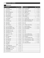
PARTS LIST 

No.  Description 

Qty.  Order No. 


No.  Description 

Qty.  Order No. 

Computer 

T7 - 001 


35 

Cushion 

T7 - 035 

Key pad


T7 - 002 


36 

M6 x 13mm Washer 

T7 - 036 

Console Support Tube 

T7 - 003 


37 

#8 x 15mm Screw 

38 

T7 - 037 

M6 x 20mm Allen Head Bolt


T7 - 004 


38 

Console Housing - Bottom 

T7 - 038 

Console Support Tube


T7 - 005 


39 

Deck Fixing Tube 

T7 - 039 

N/A 


40 

M8 x 10mm Allen Head Bolt 

T7 - 040 

Plastic Fixing Insert 

T7 - 007 


41 

Upright Plastic Shroud Left #1 

T7 - 041 

#8 x 19mm Screw 

24 

T7 - 008 


42 

Upright Plastic Shroud Left #2 

T7 - 042 

#8 x 25mm Screw 

T7 - 009 


43 

Upright Plastic Shroud Right #2 

T7 - 043 

10 

Handlebar Rear End Cap - Left # 1 

T7 - 010 


44 

Upright Plastic Shroud Right #1 

T7 - 044 

11 

Handlebar Rear End Cap - Left # 2 

T7 - 011 


45 

Side Cov er  - Left 

T7 - 045 

12 

Handlebar Rear End Cap - Right # 

T7 - 012 


46 

Side Cov er  - Right 

T7 - 046 

13 

Handlebar Rear End Cap - Right # 

T7 - 013 


47 

Power Switch Set 

T7 - 047 

14 

Handlebar Grip 

T7 - 014 


48 

M5 x 10mm Screw 

T7 - 048 

15 

Handlebar 

T7 - 015 


49 

Motor Hood 

T7 - 049 

16 

Hand Pulse Sensor 

T7 - 016 


50 

Top Maintenance Cover 

T7 - 050 

17 

Console Housing - Upper 

T7 - 017 


51 

#8 x 50mm Screw 

T7 - 051 

18 

M8 x 95mm Screw 

T7 - 018 


52 

Aluminum Side Rail 

T7 - 052 

19 

Upright - Left 

T7 - 019 


53 

Running Belt 

T7 - 053 

20 

Upright - Right 

T7 - 020 


54 

Running Deck Rear Cover 

T7 - 054 

21 

1/2" x 68mm Bolt 

T7 - 021 


55 

Rear Foot Platf orm 

T7 - 055 

22 

Plastic Spacer 

T7 - 022 


56 

Rubber Spacer - Left 

T7 - 056 

23 

M8 x 25mm Allen Head Bolt 

T7 - 023 


57 

Rubber Spacer - Right 

T7 - 057 

24 

M10 x 20mm Allen Head Bolt 

T7 - 024 


58 

Running Deck 

T7 - 058 

25 

M8 x 20mm Allen Head Bolt 

T7 - 025 


59 

Deck Rubber Cushion 

10 

T7 - 059 

26 

Adjustable Cy linder 

T7 - 026 


60 

M10 x 35mm Bolt 

T7 - 060 

27 

Upright Support Tube 

T7 - 027 


61 

M5 x 15mm Screw 

T7 - 061 

28 

M8 x 15mm Allen Head Bolt 

16 

T7 - 028 


62 

Clip 

T7 - 062 

29 

M6 x 55mm Allen Head Bolt 

T7 - 029 


63 

Elev ation Motor 

T7 - 063 

30 

M14 x 113mm Bolt 

T7 - 030 


64 

M10 Ny lon Nut 

T7 - 064 

31 

Bushing 

T7 - 031 


65 

Tension Wheel 

T7 - 065 

32 

Stabilizer 

T7 - 032 


66 

Front Vent Cov er 

T7 - 066 

33 

Base Frame 

T7 - 033 


67 

Rear Vent Cover 

T7 - 067 

34 

Running Deck Fixed Tube Sleeve 

T7 - 034 


68 

Logo Light Bracket 

T7 - 068 


Summary of Contents for MOMENTUM T7

Page 1: ...MOMENTUM T7 TREADMILL USER MANUAL...

Page 2: ...y from the treadmill at all times The treadmill should not be used by persons weighing more than 400lbs Nev er allow more than one person on the treadmill at a time Wear appropriate exercise clothing...

Page 3: ...er conditions orf rom other appliances being turned on or off To reduce the possibility of treadmill damage alway s use a surge protector not included withy our treadmill This treadmill must be ground...

Page 4: ...Clear your work area Make sure that y ou hav e cleared away a large enough space to properly assemble the unit Make sure the space is free from anything that may cause injury during assembly After th...

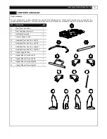
Page 5: ...nents used in the assembly of this product No Description Qty A Main Frame Assembly 1 B Front Handlebar Assembly 1 C Handlebar Assembly 2 3 Console Support Tube 1 10 Handlebar Rear End Cap Left 1 1 11...

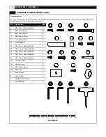
Page 6: ...ion Qty 4 M6 x 20mm Allen Head Bolt 2 8 8 x 19mm Screw 20 9 8 x 25mm Screw 8 18 M8 x 95mm Screw 2 21 1 2 x 68mm Bolt 2 22 Plastic Spacer 4 23 M8 x 25mm Allen Head Bolt 2 24 M10 x 20mm Allen Head Bolt...

Page 7: ...8 15 Handlebar 2 T7 015 49 Motor Hood 1 T7 049 16 Hand Pulse Sensor 2 T7 016 50 Top Maintenance Cover 1 T7 050 17 Console Housing Upper 1 T7 017 51 8 x 50mm Screw 2 T7 051 18 M8 x 95mm Screw 2 T7 018...

Page 8: ...7 116 83 8 x 16 x T2 0 Washer 13 T7 083 117 Motor Control Board 1 T7 117 84 Motor Hood Side Cover Left 1 T7 084 118 Motor Control Board Fan 1 T7 118 85 Motor Hood Side Cover Right 1 T7 085 119 Main Tr...

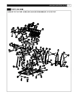
Page 9: ...RY 2 16 16 8 44 5 110 110 20 25 13 18 8 42 41 43 109 9 9 46 8 21 24 106 28 30 45 31 8 9 8 8 37 35 7 15 15 11 3 105 108 16 2 1 12 17 14 8 25 109 10 8 105 16 22 7 19 21 18 14 24 27 47 106 28 24 26 24 22...

Page 10: ...10 MOMENTUM T7 TREADMILL PARTS DIAGRAM A MAJORITY OF THE PARTS SHOWN HERE HAVE BEEN PREASSEMBLED AT THE FACTORY...

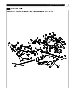
Page 11: ...www greenmasterfitness com tw 11 PARTS DIAGRAM A MAJORITY OF THE PARTS SHOWN HERE HAVE BEEN PREASSEMBLED AT THE FACTORY...

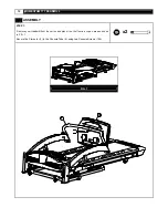
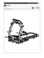
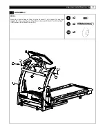
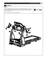
Page 12: ...T7 TREADMILL ASSEMBLY STEP 1 Remov ey our treadmill from the carton and place it on thef loor in an open area as shown in FIG 1 Secure the Computer 1 to the Console Tube 5 using two Console Screws 10...

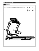
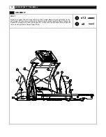
Page 13: ...www greenmasterfitness com tw 13 ASSEMBLY STEP 2 Rotate the Left and Right Uprights 19 and 20 up into position and secure them withf our M8 x 15mm Allen Head Bolts 28 x4...

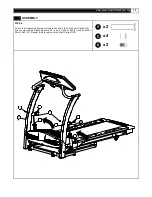
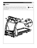
Page 14: ...14 MOMENTUM T7 TREADMILL ASSEMBLY STEP 3 Attach one Upright Cover 106 to the Left Upright 19 and secure with one M6 x 15mm Screw 107 Repeat this procedure on the Right Upright 20 x2 x2...

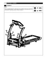
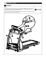
Page 15: ...15 ASSEMBLY STEP 4 Attach the Suspension System Hardware Assembly 26 to the Left Upright 19 and secure with two Plastic Spacers 22 one x 68mm Bolt 21 and one M8 x 25mm Bolt 23 Repeat this procedure on...

Page 16: ...ach one Upright Support Tube Bottom 27 to the Left Upright 19 and secure using two M10 x 20mm Allen Head Bolts 24 at the top bracket and one M8 x 15mm Allen Head Bolt 28 at the bottom bracket Repeat t...

Page 17: ...ess com tw 17 ASSEMBLY STEP 6 Attach the Console Support Tube 3 to the Console 1 Left Upright 19 and Right Upright 20 Secure using two M6 x 20mm Allen Head Bolts 4 two Metal Caps 109 and two M8 x 95mm...

Page 18: ...Left 1 41 and Upright Plastic Shroud Left 2 42 to the Left Upright 19 and secure with six 8 x 19mm Screws 8 and four 8 x 25mm Screws 9 Repeat the procedure on the Right Upright 20 to attach the Uprig...

Page 19: ...se Sensor Wires Upper 112 to the Hand Pulse Sensor Wires 16 as shown NOTE Make sure all wires are recessed into the tube do not trap or pinch any of the wires Attach the Front Handlebar 108 to the Con...

Page 20: ...Motion Console Sensor Wire 6 coming from the Handlebar 15 as shown NOTE Make sure all wires are recessed into the tube do not trap or pinch any of the wires Attach one Handlebar 15 to the Left Upright...

Page 21: ...andlebar Rear End Cap Left 2 11 to the Left Upright 19 Secure using four 8 x 19mm Screws 8 Repeat the procedure on the Right Upright 20 to attach the Handlebar Rear End Cap Right 1 12 and Handlebar Re...

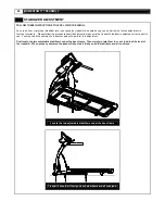
Page 22: ...make sure the treadmill stabilizer is adjusted correctly priorto use You may need the assistance of another person to perform this adjustment First locate the two adjustable stabilizers under the bas...

Page 23: ...so that the treadmill rests on thef ront transportation wheels Roll to a desired location After moving the treadmill alway s be sure to follow the STABILIZER ADJUSTMENT instructions to lev el the tre...

Page 24: ...24 MOMENTUM T7 TREADMILL...

Page 25: ...ndow will display 0 SLEEP DISPLAY MODE When the power is ON the computer will automatically enter SLEEP MODE if it is left idlef or 3 minutes without receiv ing any input Press any button to return to...

Page 26: ...D UP DOWN button to change the speed Press the INCLINE UP DOWN button to elev ate the treadmill The TIME CALORIES and DISTANCE will count upf rom 0 PAUSE STOP During the workout press the STOP button...

Page 27: ...ow the preset time as 30 00 and blink After press the button Press the SPEED UP DOWN buttons to set your ideal workout time then press the ENTER button to conf irm Then press the START button to start...

Page 28: ...tion Time Distance Calories is paused To recall values and resume exercising press START Pressing the STOP button again within 30 seconds returns all data to zero and the computer returns to POWER ON...

Page 29: ...H MAX SPEED MPH 1 1 8 3 0 2 2 0 3 4 3 2 2 3 8 4 2 4 4 2 5 2 6 4 6 6 2 8 5 0 7 3 0 5 4 8 3 2 5 8 9 3 4 6 2 10 3 6 6 6 11 3 8 7 0 12 4 0 7 2 WEIGHT LOSS When the treadmill is in PROGRAM SELECT status pr...

Page 30: ...ending the prev iously saved workout time Simply press the SPEED UP DOWN and INCLINE UP DOWN buttons to change the speed and incline lev el during the workout then f ollow the SET AND SAVE procedure a...

Page 31: ...to zero If the 3 rd WARM UP program still cannot bring up the actual pulse rate to the minimum target workout heart rate the program will stop and SPEED LED will show FAIL HEART RATE CONTROL MAIN PRO...

Page 32: ...e center Repeat the above procedure until the walking belt is centered It may be necessary to set walking belt tension oncey ou hav e completed this procedure if the belt feels like it is slipping whi...

Page 33: ...ormance Your treadmill should not hav e to be lubricated usually within the f irst y ear or 400 hours of use Ev ery 2 months of operation lift the sides of the walking belt andf eel the top surface of...

Page 34: ...rcise only for af ew minutes iny our target zone Howev er y our aerobic f itness will improv e ov er the next six to eight weeks Don t be discouraged if it takes longer It s important to work at your...

Page 35: ...condition To determine your target zone consult the chart we hav e prov ided FIND YOUR TARGET HEART RATE 200 180 160 140 120 100 YOUR HEART RATE in beats per minute 80 20 25 30 35 40 45 50 55 60 65 70...

Page 36: ...primarily lower body muscle groups These muscle groups are shown in gray color on the chart below MUSCLE GROUPS A Shoulder muscles Calf muscles G B Pectoral muscles Trapezius muscles H C Bicep muscle...

Page 37: ...nner Thigh Stretch Sit with the soles of y ourf eet together withy our knees pointing outward Pully our f eet as close intoy our groin as possible Gently push y our knees towards the floor Hold f or 1...

Page 38: ...reset or hav e an electrician replace the breaker in home 4 Hav e an electrician check for inadequate voltage at the outlet Treadmill looses power during use 1 Check the circuit breaker reset switch l...

Page 39: ...Industrial Corp All rights reser ved MOMENTUM SERIES products are manuf actured by GREENMASTER INDUSTRIAL CORP No 1 Lane 233 Sec 2 Charng Long Road Taiping City Taichung Hsien Taiwan R O C Website www...

Reviews: