5990A
9
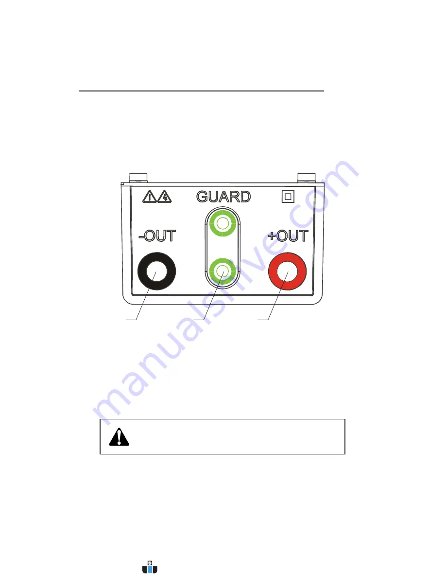
The 5990A Tester contains the following connections:
• Four banana safety sockets for test leads
(Fig. 3)
.
• Socket for mains supply cable (
Fig. 4)
.
Fig. 3
Test Leads Connector Diagram
Connectors
1..........
(-OUT):
Negative Insulation Resistance test terminal
2..........
GUARD:
Guard terminals are intended to lead away potential leakage current while
measuring the Insulation. Both green sockets are connected together inside of
the instrument.
3..........
(+OUT):
Positive Insulation Resistance test terminal
Use original test accessories only!
Max allowed external voltage between test terminals and ground is 600V!
Max allowed external voltage between test terminals is 600V!
Instrument Description
(cont’d)
1
2
3
www.calcert.com
1.888.610.7664
0
5
10
15
20
25
30


