Greenlee Textron / Subsidiary of Textron Inc.
15
4455 Boeing Dr., Rockford, IL 61109-2988 815/397-7070
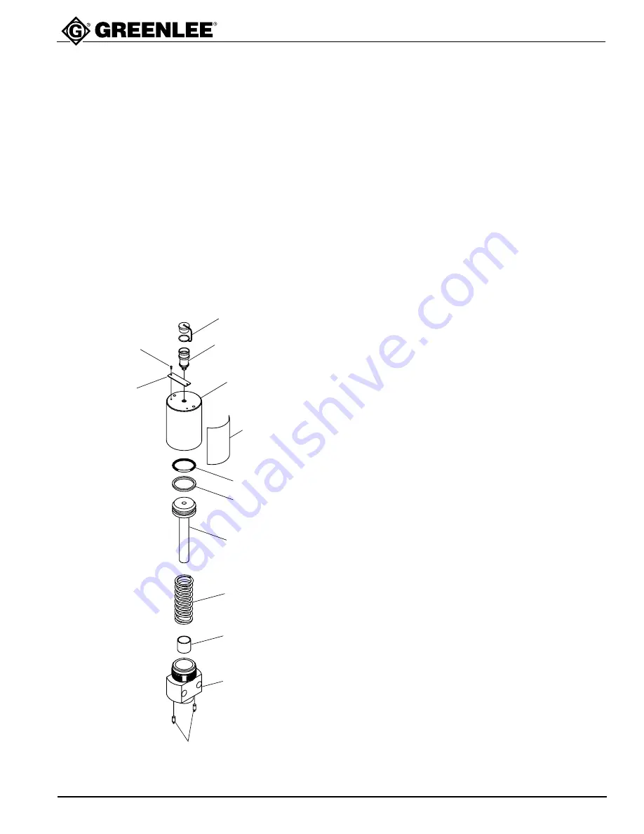
Bus Bar Punch System
Ram Unit (503 7735.3)
3
4
5
6
7
8
10
2
1
11
12
13
9
Key
Part No.
Description
Qty
1
503 7948.8
Serial Plate ............................... 1
2
905 2760.7
Drive Screw .............................. 2
3
905 4168.5
Dust Plug .................................. 1
4
905 4167.7
Threaded Coupler .................... 1
5
503 7739.6
Cylinder .................................... 1
6
503 9050.3
Caution Decal ........................... 1
7
905 4191.0
O-Ring ...................................... 1
8
905 4190.1
Backup Ring ............................. 1
9
503 7738.8
Piston ....................................... 1
10
503 7740.0
Return Spring ........................... 1
11
905 4340.8
Self-Lubricating Bearing ........... 1
12
503 7737.0
Cylinder Base ........................... 1
13
905 4164.2
Spring Plunger ......................... 2
Disassembly
1.
Clamp the cylinder base unit (12) into a vise and
unthread the cylinder (5).
2.
Carefully lift the cylinder from the cylinder base.
3.
Remove the spring (10).
4.
Carefully remove the piston (9) from the cylinder
bore. Do not scratch the bore surface.
5.
Remove and replace the O-ring (7) back-up ring (8).
6.
Unscrew the spring plungers (13).
7.
Slide the bearing (11) out of the cylinder base (12).
8.
Unthread the coupler (4).
9.
Serial plate (1) is riveted with two drive screws (2).
Assembly
1.
Press the bearing (11) into the bore of the cylinder
base (12).
2.
Thread the two spring plungers (13) into the base.
The body of each spring plunger must be below the
surface of the base.
3.
Use an O-ring lubricant to lubricate the O-ring (7)
and backup ring (8), and assemble to the piston (9);
slide the piston into the cylinder (5) bore.
4.
Clamp the cylinder base (12) into a vise.
5.
Slip the spring (10) over the piston in the cylinder.
Position the cylinder (5) over the cylinder base (12)
so that the piston (9) is aligned with the bearing (11).
6.
Compress the spring by pressing the cylinder down
over the base. Thread the cylinder onto the base.
Torque to 150 foot-pounds (203.36 Nm).
7.
Attach the serial plate (1) with two drive screws (2).
8.
Slide the key ring of the dust plug (3) over the
threaded end of the coupler (4). Apply a hydraulic
thread sealer such as BAKERSEAL to the pipe
threads of the coupler (4), and thread the coupler
into the end of the cylinder (5).


