background image

SECTION 3.0: Installation

3.1 INSPECTION

Carefully remove the Vari-Green probe(s) or station and transmitter from the shipping container and inspect for any 
damage.

IMPORTANT: All Vari-Green transmitters are factory configured with the application specific duct size 
and flow rate information. The transmitter and probes or flow station are tagged with matching ESID and/
or customer specific identification. Matching the systems as configured by the factory will reduce the 
installation and start-up labor required.

Review the Factory Set-Up Information Sheet provided separately and verify that the W.O. # and serial # match 
those on the Vari-Green

 system. 

Verify that the configuration recorded on the Factory Set-Up Information Sheet is 

correct for your application. If any damage has occurred in transit or the factory set-up configuration is incorrect for 
your application, please contact Greenheck at 1-800-717-6540.

3.2 INSTALLATION LOCATION GUIDELINES

The standard version of the Vari-Green transmitter and probe connection heads have a NEMA 1 enclosure rating 
suitable for clean and dry indoor locations. For additional protection, an enclosure with an adequate NEMA rating 
may be required.
The ambient temperature of the selected mounting location must be between -20°F and 140°F. Consideration should 
be given to units exposed to direct sunlight.
The selected mounting location should be rigid and free of vibration.

3.3 TRANSMITTER PLACEMENT AND MOUNTING

For placement of transmitter, see instruction manual at www.greenheck.com, 478799 AMD-XX-TD IOM.

3.4 POWER and SIGNAL CONNECTIONS

NOTE:

 The Vari-Green transmitter terminal connections for power and signal wire are labeled on the board for 

installation convenience. Power wiring is located at terminal strip J4. Signal wiring is located at terminal strip J1.
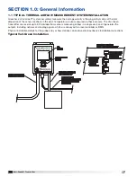
The REMOVABLE* terminal strips for power and signal are located in the lower portion of the transmitter and are 
accessible by opening the hinged cover. (See figure 

below 

for the exact location of the terminal strips.) Two conduit 

openings are provided in the bottom of the transmitter enclosure; one for power and one for signal wiring.
Recommended wire gauge (14 AWG is the maximum wire gauge - no more than two wires recommended per 
terminal):
Power wire = 14 AWG to 18 AWG 
Signal wire = 14 AWG to 22 AWG
* To aid in the wiring of both power and signal wires, J1 and J4 are removable by pulling the terminal strip straight 
up and off the circuit board. Once wiring has been completed, replace the terminal strip by aligning it with the 
receptacle and inserting firmly.

WARNING: The Vari-Green transmitter is a low voltage device (24V AC/DC). Connecting the transmitter to 
high voltage power (e.g. 110 VAC) may cause damage and will void the warranty.
Power Connections:

 Terminal J4, pin 1 for Line, pin 2 for Neutral and pin 3 for Ground. See figure below for details. 

The Vari-Green can be powered by either 24VAC providing 20-28VAC or 24VDC providing 20-40VDC.

CAUTION: The earth ground is required on all Vari-Green transmitter installations. Omitting the connection to 
earth ground could result in poor performance and may void the warranty.
Analog Outputs:

 Terminal J1; AO1 pins 1 and 2; AO2 pins 3 and 4. Pins 2 and 4 are for the common wire of the 

respective output. See figure below for details. 

Vari-Green® Transmitter

4

®

Summary of Contents for AMD-TD Series

Page 1: ...y for the customer s failure to comply with these requirements If this product is used in a manner not specified in this manual the protection providied by this product may be impaired Regarding This Manual This manual should be passed on to the end user Before use read this manual thoroughly to comprehend its contents The contents of this manual may be changed without prior notice All rights rese...

Page 2: ...s also measured via these sensors The Vari Green transmitter can receive up to 32 individual flow sensors measuring airflow in a single duct and it generates the outputs including network and analog signals which are conveyed to a local controller or BMS Physical installation details for the probe array or flow stations can be found in Greenheck s Installation Instructions Typical Vari Green Insta...

Page 3: ...r APPROVALS UL 60730 PENDING BTL FCC Part 15 Subpart B Class A Device 2 1 PROBE ASSEMBLY INDIVIDUAL SENSOR ACCURACY Velocity 2 of reading from 0 5000 FPM Temperature 0 1 F Multi point NIST traceable calibration of both temperature and velocity SENSOR TYPE Her metically sealed precision matched thermistors with laser trimmed resistive heating element mounted in flow conditioning aperture Max number...

Page 4: ... 4 POWER and SIGNAL CONNECTIONS NOTE The Vari Green transmitter terminal connections for power and signal wire are labeled on the board for installation convenience Power wiring is located at terminal strip J4 Signal wiring is located at terminal strip J1 The REMOVABLE terminal strips for power and signal are located in the lower portion of the transmitter and are accessible by opening the hinged ...

Page 5: ... FPM set point drives display and output to zero Alarm Alert Configuration Configure alarm type upper and lower limits Network Configuration Configure network type baud rate and address information Field Characterization For information on field characterization please see section below SERVICE MENU SELECTION DESCRIPTION Password Configuration Enable disable and change password Total System Scan D...

Page 6: ... ID can be entered through the Service Menu It is typically used to describe the transmitter location in the building Brightness Allows the user to set the brightness of the display in real time Inactivity Timeout The time period which holds the display in menu mode When the timer expires the display is returned to the main display screen showing the process values Analog Output Configuration The ...

Page 7: ...nable Reg Alerts will turn ON OFF Enable Global Alerts will turn ON OFF Field Characterization Field characterization K factoring of a flow element is the adjustment of the flow measurement system to match a known reference measurement most commonly airflow traverse testing Field characterization is typically done when there is insufficient straight duct run or another issue that creates questiona...

Page 8: ... See below for sensor control If Missing yellow is at a value other than zero the transmitter is not communicating with the associated node Sensor Control An enabled sensor will report measurement data to the Vari Green transmitter This is the default condition after initially powering the system A disabled sensor will not report measurement data to the Vari Green transmitter Disabled sensors may ...

Page 9: ...xternal 24 VAC 24 VDC power source 1 Press the power button located on the bottom left corner of the front cover to turn the system ON 2 The display will show a loading bar After reaching 100 the display will indicate which sensors have been discovered for approximately 2 seconds Then the normal operating screen will be displayed The default normal operating screen will display Total Flow on the f...

Page 10: ... controller ceases to receive valid airflow and or temperature signals make certain the following have been checked and confirmed The power wiring is securely connected to the proper terminals and is providing the intended 24V AC DC power The signal wiring is securely connected to the proper terminals The probe to probe and probe to transmitter cables and connections are properly connected and sec...

Reviews: