background image

S2S KNX Gateway

19

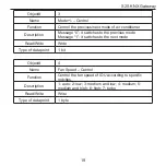
Object#

3

Name

Mode+/- – Control

Function

Control the previous/next mode of air conditioner

Description

Message “0”: it switches to the previous mode

Message “1”: it switches to the next mode

Read/Write

Write

Type of data point

1 bit

Object#

4

Name

Fan Speed – Control

Function

Control the fan speed of IDU according to specific 

notches.

Description

1: auto; 2: low; 3: medium and low; 4: medium; 5: 

medium and high; 6: high; 7: turbo

Read/Write

Write

Type of data point

1 byte

Summary of Contents for ME30-24/F1 K

Page 1: ...S2S KNX Gateway Model ME30 24 F1 K ...

Page 2: ...the appliance Children should be supervised to ensure that they do not play with the appliance 2 This instruction manual is a general version some functions are only applicable to specific product so all the illustrations and information in the instruction manual are only for reference the control interface should be subject to the actual product 3 In order to better meet the customers demand our ...

Page 3: ...ed national laws regulations and industrial standards violation of any stipulations of this instruction manual etc 5 The final authority for the interpretation of this instruction manual belongs to Gree Electric Appliances Inc of Zhuhai ...

Page 4: ...es 1 2 Display 3 3 Introduction to Functions 4 4 Wire Connection and Installation 6 5 ETS5 Configuration 9 6 ETS System Parameters 11 7 Instruction of KNX Communication Objects 18 8 Product Specification 29 9 Error Code 31 ...

Page 5: ... electric shock 2 Insert the socket only after ensuring the socket of power cord is dry and clean 3 Before touching the electric components please make sure that the appliance is power failed 4 Please do not touch this appliance with wet hands which may cause electric shock 5 Please use the power cord with designated specification poor contact or improper installation may cause fire hazard 6 Power...

Page 6: ...therwise it may cause communication error 3 Make sure that the communication wire is connected into the correct interface otherwise it may cause communication error 4 After connecting the wires please use insulated adhesive tape to protect the wire to prevent oxidation or short circuit 5 Requirement for normal working environment of S2S KNX Gateway Temperature 0 45 Humidity less than 85 except for...

Page 7: ...Gateway can connect Gree air conditioner into KNX system Compatibility All IDUs of GMV5 series for export Major features 1 Save space it is installed inside the electric control cabinet 2 Fast and concealed installation 3 No need to supply extra power ...

Page 8: ...indicator will be on constantly if there is communication error between S2S KNX Gateway and the unit the indicator is off RUN indicator if the S2S KNX Gateway works normally RUN indicator flashes Prog indicator when the indicator is on it means the S2S KNX Gateway is under programming status when the indicator is off it means the S2S KNX Gateway quits programming status 3 2 Functional Dial Codes S...

Page 9: ...he first bit is in ON end it is set as slave HBS equipment The second bit of functional dialer S1 is reserved master HBS equipment slave HBS equipment Remark the default S2S KNX Gateway is master HBS equipment When there is multiple equipment in the HBS bus bar it is recommended to set the S2S KNX Gateway as slave equipment the wired controller as master equipment ...

Page 10: ...hysical address of equipment is altered via ETS5 please press the program button ETS5 will prompt to make the S2S KNX Gateway enter into program status module program indicator is on 4 Wire Connection and Installation Connect to IDU First cut off the power of IDU Open the interface panel of IDU and find the HomeBus wire terminals H1 H2 and use twisted pair to connect the H1 and ...

Page 11: ...ommunication wire L m Wire diameter mm2 Material standard Remark Shielding light general PVC sleeve twisted pair copper core soft wire RVVSP L 250 2 0 75 IEC 60227 5 2007 When the unit is installed in the environment with strong magnetism or strong interference it should adopt RVVSP It can work with wired controller Topological graph is shown as below Fig 4 1 Wire connection for HBS single equipme...

Page 12: ...ateway to the KNX system bus bar KNX and connect the KNX black to the KNX system bus bar KNX there is requirement for polarity Requirement of communication wire material Material and length of communication wire should be selected according to KNX standard strictly Installation Adopt standard 35mm guide rail installation method as shown as below ...

Page 13: ...S5 Product database and related data of S2S KNX Gateway can be acquired from the following website http gbms gree com Please read the downloaded Readme txt inside the zip package before using The content of Readme txt include the installation method of product database of S2S KNX Gateway After importing the database of S2S KNX Gateway to ETS5 it will display the communication objects as shown in F...

Page 14: ...S2S KNX Gateway 10 Fig 5 1 Communication Objects ...

Page 15: ...system parameter in the next section select Disable to turn off the object 27 6 ETS System Parameters 6 1 Setting Interface of General Parameters Setting interface of General parameters is shown as Fig 6 1 here set the action and ON OFF of some functions after the air conditioner is energized Fig 6 1 Setting interface of General parameters ...

Page 16: ...unction of disable object When the value is 1 the function is activated user can send the command to select whether to shield the command via ETS when the value is 0 the function is not available Parameter Support 1Bit Up Down Set Mode This parameter is to set if the and function of mode is available Parameter Support 1Bit Up Down Fan Speed This parameter is to set if the and function of fan speed...

Page 17: ... Scene This parameter is to set if activate the scene function After activating this function the Scene parameter setting card will appear as shown in Fig 6 2 6 2 Setting Interface of Scene Parameter Setting interface of Scene parameter is shown as Fig 6 2 Here can set the function of each scene There are a total 4 scenes the settable options of each scene are the same ...

Page 18: ...o set the scene No of the first scene the number is within 1 64 1 and 64 are included the other three scenes are in the same rule Parameter Enable storage scene This parameter is to set if the saving function of the first scene is available After activating such function it can re save the scene via ETS software use the ...

Page 19: ...pearture 16 30 This parameter is to set the setting temperature of the first scene the other three scenes are in the same rule Parameter Mode This parameter is to set the mode of the first scene the other three scenes are in the same rule Parameter Fan Speed This parameter is to set the fan speed of the first scene the other three scenes are in the same rule 6 3 Setting Interface of Status Paramet...

Page 20: ... forwardly send the status message to the bus bar if you want to view the function status please send the reading command via ETS Functional option Send after change When certain function select such option if the function status is changed or after sending the control command the gateway will send status message to ...

Page 21: ...us bar Functional option Cyclic When certain function select such option the function status message will be sent to bus bar in a period of time the interval can be set via Period of send 5 5000 s only within 5 5000 can be set ...

Page 22: ...onditioner Description Message 1 ON Message 0 OFF Read Write Write Type of data point 1 bit Object 2 Name Mode Control Function Control operating mode of air conditioner Description 1 cooling 2 dehumidifying 3 air supply 4 heating 5 auto 6 floor heating 7 3D heating 8 space heating Read Write Write Type of data point 1 byte ...

Page 23: ...tches to the previous mode Message 1 it switches to the next mode Read Write Write Type of data point 1 bit Object 4 Name Fan Speed Control Function Control the fan speed of IDU according to specific notches Description 1 auto 2 low 3 medium and low 4 medium 5 medium and high 6 high 7 turbo Read Write Write Type of data point 1 byte ...

Page 24: ...ite 0 the fan speed will return to auto 2 Message 1 each time writing 1 for once the fan speed will switch to the next notch when the fan speed is auto write 1 the fan speed will return to turbo Read Write Write Type of data point 1 bit Object 6 Name Vanes U D Swing Control Function Control the ON OFF of up and down swing of air conditioner Description Message 1 ON Message 0 OFF Read Write Write T...

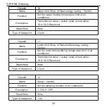
Page 25: ...int Temperature Control Function Set the temperature of air conditioner Description Transmission value actual value actual value 16 0 30 0 Read Write Write Type of data point 2 byte Object 9 Name Lower limit Temp of Cool energy saving Control Function Set the lower cooling temperature limit of air conditioner Description Transmission value actual value actual value 16 0 30 0 Reserved Read Write Wr...

Page 26: ...rite Type of data point 2 byte Object 11 Name Lower limit Temp of Dehumidify energy saving Control Function Set the lower dehumidifying temperature limit of air conditioner Description Transmission value actual value actual value 16 0 30 0 Reserved Read Write Write Type of data point 2 byte Object 12 Name Sleep Control Function Set the sleeping function of air conditioner Description 1 ON 0 OFF Re...

Page 27: ...ype of data point 1 bit Object 14 Name Ventilation Control Function Set the air exchange function of air conditioner Description 1 ON 0 OFF Read Write Write Type of data point 1 bit Object 15 Name On Off Status Function Feed back the ON OFF status of the current air conditioner Description 1 ON 0 OFF Read Write Read Type of data point 1 bit ...

Page 28: ... low 05 medium 06 medium and high 07 high 08 ultra high Read Write Read Type of data point 1 byte Object 17 Name Mode Status Function Feed back the operating status of the current air conditioner Description 01 cooling 02 dehumidifying 03 air supply 04 heating 05 auto cooling 06 auto heating 07 floor heating 08 3D heating 09 space heating Read Write Read Type of data point 1 byte ...

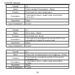
Page 29: ...it reads 12 it means the unit has activated the low temperature dehumidifying function When 8 heating or low temperature dehumidifying are activated user can turn off the corresponding function via other equipment or switchover mode Read Write Read Type of data point 2 byte Object 19 Name Outdoor ambient Temperature Status Function Feed back the outdoor temperature Description Transmission value a...

Page 30: ...ror Code Status Function Feed back error of unit Description The lower 8 bit and higher 8 bit are two ASCII code respectively 0 refers to no error code Read Write Read Type of data point 2 byte Object 22 Name Project No of starting indoor uint of gateway Status Function Feed back the engineering number of the current connected IDU Description Transmission value actual value actual value 1 255 Read...

Page 31: ...Read Write Read Type of data point 1 byte Object 24 Name Machine operation mode Status Function Feed back operating mode of air conditioner Description Transmission value actual value actual value 02 cooling mode 05 heating mode Read Write Read Type of data point 1 byte Object 25 Name Remote lock Status Function Feed back long distance locking status of air conditioner Description 0 OFF 1 ON Read ...
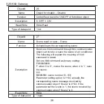
Page 32: ...s communication object can invoke or save the scene of air conditioner The following will explain the meaning of 8 bit command in detail Set one 8bit command as binary coding FXNNNNNN F when it is 0 invoke the scene when it is 1 save the scene X 0 NNNNNN scene number 0 63 Parameter setting option is 1 64 actually the corresponding scene message received by communication object Scene is 0 63 If the...

Page 33: ...S2S KNX Gateway 29 8 Product Specification ...

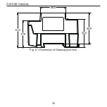
Page 34: ...S2S KNX Gateway 30 Fig 8 1 Dimension of Gateway unit mm ...

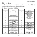
Page 35: ...ature protection JA Pressure error protection E3 Low voltage protection JC Water flow switch protection E4 High air discharge temperature protection of compressor JL Low pressure protection F0 Mainboard of ODU is faulted b2 Defrosting temperature sensor 1 error F1 High pressure sensor error b3 Defrosting temperature sensor 2 error F3 Low pressure sensor error JE Oil return tube is blocked F5 Air d...

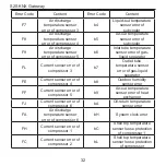
Page 36: ...ror of compressor 3 b7 Outlet tube temperature sensor error of gas liquid separator FE Current sensor error of compressor 4 b8 Outdoor humidity sensor error FF Current sensor error of compressor 5 b9 Air out temperature sensor error of heat exchanger FJ Current sensor error of compressor 6 bA Oil return temperature sensor error FA Air discharge temperature sensor error of compressor 6 bH System cl...

Page 37: ...r J1 Compressor 1 overcurrent protection P0 Compressor driver board error J2 Compressor 2 overcurrent protection P1 Compressor driver board working error J3 Compressor 3 overcurrent protection P2 Compressor driver board power voltage protection J4 Compressor 4 overcurrent protection P3 Compressor driver board reset protection J5 Compressor 5 overcurrent protection H0 Fan driver board error J6 Comp...

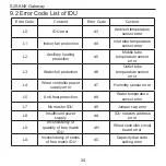
Page 38: ...sor error L3 Water full protection d6 Outlet tube temperature sensor error L4 Wired controller power supply error d7 Humidity sensor error L5 Anti frost protection d8 Water temperature sensor error L7 No master IDU d9 Jumper cap error L8 Insufficient power supply dA IDU network address error L9 Inconsistency of quantity of free match IDU dH Wired controller circuit board error LA Inconsistency of ...

Page 39: ...Code Content LH Bad air quality alarm dL Air out temperature sensor error LC Unmatched model of IDU and ODU dE Indoor CO2 sensor error LP PG motor zero passage error db Special code engineering debugging code d1 Indoor electric circuit is faulted ...

Page 40: ...ction alarm U5 Compressor driver board address error C6 Alarm for inconsistency of ODU quantity U6 Valve abnormity alarm CH High rated capacity allocation U8 IDU pipeline error CL Low rated capacity allocation U9 ODU pipeline error CF Multiple master control units error UC Successful setting of master IDU CJ System address dial codes confliction UE Invalid refrigerant charging CP Multiple master w...

Page 41: ...eway 37 Code Content Code Content C0 Communication error between IDU and ODU IDU and wired controller Cb Overflow of unit IP address C2 Communication error between master controller and inverter compressor driver ...

Page 42: ...operation A2 After sales refrigerant reclamation operation Ad Operation limitation A3 Defrosting An Anti high temperature control A4 Oil return n3 Compulsory defrosting A5 Online testing n5 Compulsory IDU engineering number excursion A8 Vacuum pumping mode nL Object low pressure revision AH Heating nJ Anti high temperature for heating AC Cooling nP Defrosting temperature adjusting value ...

Page 43: ...S2S KNX Gateway 39 Code Content Code Content AF Air supply nU Clear out IDU long distance shielding command AJ Filter washing remind ...

Page 44: ...S2S KNX Gateway 40 GREE ELECTRIC APPLIANCES INC OF ZHUHAI Add West Jinji Rd Qianshan Zhuhai Guangdong China 519070 Tel 86 756 8522218 Fax 86 756 8669426 E mail gree gree com cn www gree com ...

Reviews: