Water-cooled Heat Recovery DC Inverter VRF
51
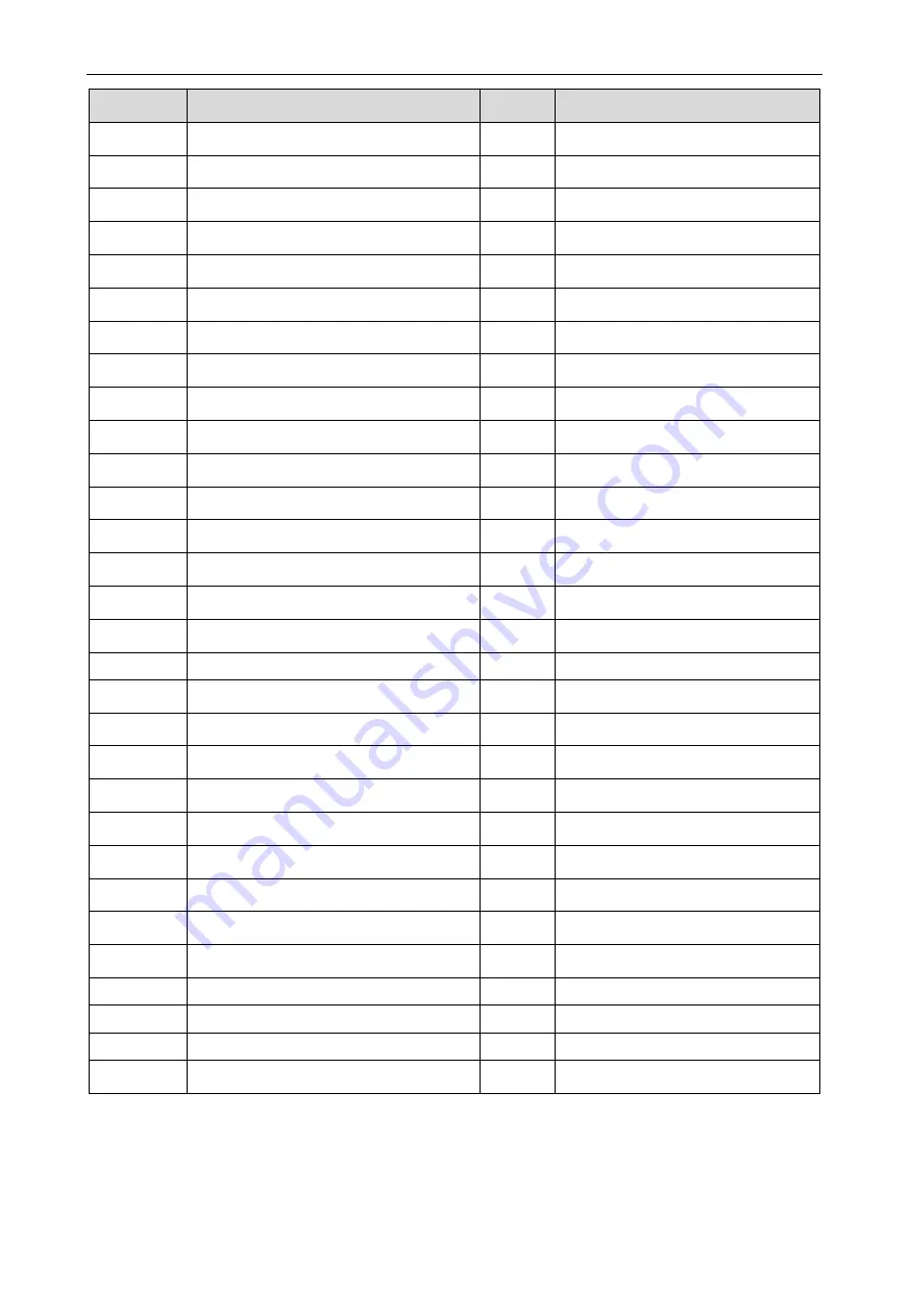
Error Code
Content
Error
Code
Content
JF
Oil-return pipe is leaking.
b9
Malfunction of gas temperature sensor
of heat exchanger inlet.
bd
Malfunction of gas-in temperature sensor of
sub-cooler.
by
Malfunction of water-out of heat
exchanger.
P0
malfunction of driving board of compressor.
bA
Malfunction of oil-return temperature
sensor 1.
P1
Driving board of compressor operates
abnormally.
bH
Clock of system is abnormal.
P2
Voltage protection of driving board power of
compressor.
bE
Malfunction of inlet tube temperature
sensor of condenser.
P3
Reset protection of driving module of
compressor.
bF
Malfunction of outlet tube temperature
sensor of condenser.
P4
Drive PFC protection of compressor.
bJ
High-pressure sensor and low-pressure
sensor are connected reversely.
P5
Over-current protection of inverter
compressor.
bP
Malfunction of temperature sensor of
oil-return 2.
P6
Drive IPM module protection of compressor.
bU
Malfunction of temperature sensor of oil
return 3.
P7
Malfunction of drive temperature sensor of
compressor.
bb
Malfunction of temperature sensor of oil
return 4.
P8
Drive IPM high temperature protection of
compressor.
H0
Malfunction of driving board of fan.
P9
Desynchronizing protection of inverter
compressor.
H1
Driving board of fan operates
abnormally.
PA
Malfunction of drive storage chip of
compressor.
H2
Voltage protection of driving board
power of fan.
PH
High-voltage protection of compressor’s
drive DC bus bar.
H3
Reset protection of driving module of
fan.
PC
Malfunction of current detection circuit drive
of compressor.
H4
Drive PFC protection of fan.
PL
Low voltage protection for DC bus bar of
drive of compressor.
H5
Over-current protection of inverter fan.
PE
Phase-lacking of inverter compressor.
H6
Drive IPM module protection of fan.
PF
Malfunction of charging loop of driven of
compressor.
H7
Malfunction of drive temperature sensor
of fan.
PJ
Failure startup of inverter compressor.
H8
Drive IPM high temperature protection
of fan.
PP
AC current protection of inverter
compressor.
H9
Desynchronizing protection of inverter
fan.
PU
AC input voltage of drive of inverter
compressor.
HA
Malfunction of drive storage chip of
inverter outdoor fan.
F0
Main board of ODU is poor.
HH
High-voltage protection of fan’s drive
DC bus bar.
F1
Malfunction of high-pressure sensor.
HC
Malfunction of current detection circuit
of fan drive.
F3
Malfunction of low-pressure sensor.
HL
Low voltage protection of bus bar of fan
drive.
F5
Malfunction of discharge temperature
sensor of compressor 1.
HE
Phase-lacking of inverter fan.
F6
Malfunction of exit-tube temperature sensor.
HF
Malfunction of charging loop of fan
drive.
F7
Malfunction of humidity sensor.
HJ
Failure startup of inverter fan.
F8
Malfunction of water temperature sensor.
HP
AC current protection of inverter fan.
F9
Malfunction of jumper cap.
HU
AC input voltage of drive of inverter fan.
FA
Web address of IDU is abnormal.
Fy
Malfunction of water-in of heat
exchanger.
Summary of Contents for GMV-WQ120WM/A-F
Page 58: ......


