background image

Champaign, Illinois

(217) 398-8970, Ext 5

[email protected]

READ THROUGH THIS MANUAL BEFORE STARTING CONSTRUCTION. IT CONTAINS IMPORTANT

INSTRUCTIONS AND WARNINGS CONCERNING THE ASSEMBLY AND USE OF THIS MODEL.

WARRANTY

Great Planes

®

 Model Manufacturing Co.

 guarantees this kit to 

be free from defects in both material and workmanship at the 
date of purchase. This warranty does not cover any component 
parts damaged by use or modification. 

In no case shall Great 

Planes’ liability exceed the original cost of the purchased kit.


Further, Great Planes reserves the right to change or modify this 
warranty without notice.

In that Great Planes has no control over the final assembly or 
material used for final assembly, no liability shall be assumed nor 
accepted for any damage resulting from the use by the user of 
the final user-assembled product. By the act of using the 
user-assembled product, the user accepts all resulting liability.

If the buyer is not prepared to accept the liability associated 
with the use of this product, the buyer is advised to return 

this kit immediately in new and unused condition to the 
place of purchase.

To make a warranty claim send the defective part or item to 
Hobby Services at the address below:

Hobby Services

3002 N. Apollo Dr.  Suite 1

Champaign IL  61822  USA

Include a letter stating your name, return shipping address, as 
much contact information as possible (daytime telephone 
number, fax number, e-mail address), a detailed description of 
the problem and a photocopy of the purchase receipt. Upon 
receipt of the package the problem will be evaluated as quickly 
as possible.

Wingspan:

55 in [1395 mm]

Weight:

5.5– 6.5 lb [2493– 2947 g]

Length:

49.5 in [1255mm]

Wing Area:

564 in

[36.4 dm

2

Wing Loading:

22– 26 oz /ft

2

[67– 79 g /dm

2

]

SPECIFICATIONS

INSTRUCTION  MANUAL

Radio:

5 channel radio

Engine:

.46 - .55


[ 7- 9 cc] 2-stroke glow engine,

.70 (11.5 cc) 4-stroke glow engine

Motor:

Great Planes RimFire .55
(42-60-480) Outrunner Brushless

GPMA1015

© 2016 Great Planes Model Mfg. A subsidiary of Hobbico,

®

 Inc.

Summary of Contents for ULTRA SPORT 46

Page 1: ...er accepts all resulting liability If the buyer is not prepared to accept the liability associated with the use of this product the buyer is advised to return this kit immediately in new and unused co...

Page 2: ...contact your local authorities to find out the latest rules and regulations In the United States please visit knowbeforeyoufly org faa gov uas SAFETY PRECAUTIONS Protect Your Model Yourself Others Fo...

Page 3: ...t manufacturer provide you with a top quality thoroughly tested product and instructions but ultimately the quality and flyability of your finished model depends on how you build it therefore we canno...

Page 4: ...rite 21st Century Trim Sealing Iron COVR2750 Optional Supplies and Tools Here is a list of optional tools mentioned in the manual that will help you build the Ultra Sport 46 EP 2 oz 57g spray CA activ...

Page 5: ...parts are not available from Product Support but can be purchased from hobby shops or mail order Internet order firms Hardware items screws nuts bolts are also available from these outlets To locate...

Page 6: ...pply a few drops of thin CA to each side of the hinge 2 Tighten the covering with a covering iron set on low temperature as needed ASSEMBLE THE WING Aileron Servo Installation Begin with the left wing...

Page 7: ...o into the receiver Switch on the transmitter and connect a receiver battery to the receiver Center the aileron servo trim Install the servo horn 6 Install the nylon clevis 7 Attach clevis to control...

Page 8: ...8 9 Mount control horn 10 Install the Faslink 11 Repeat steps 1 10 to install the aileron servo in the right wing...

Page 9: ...halves together to check the fit Make sure both wing halves fit together at the root without any gaps 6 Gather everything needed to glue the two wing halves together including 30 minute epoxy mixing s...

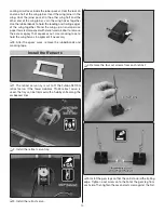
Page 10: ...zes out Use masking tape to hold the wing halves in alignment if necessary 8 After the epoxy cures remove the rubberbands and masking tape Install the Retracts 1 The retract servo tray is cut to fit t...

Page 11: ...position the retracts in the wheel wells Move the wheels up and down making adjustments so that the wheels do not hit the wing sheeting NOTE If using a glow engine coat the inside of the wheel wells w...

Page 12: ...the two set screws in the screw lock connectors Check that the retracts lock in the up and the down positions with no binding of the servo ASSEMBLE THE FUSELAGE Install the Tail 1 Install the wing 2 R...

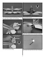
Page 13: ...lel If they are not lightly sand the stabilizer slot of the fuselage 7 Install the horizontal stabilizer 8 Install the vertical fin 9 Cut the covering from over the tail gear bushing slot 10 Apply a d...

Page 14: ...e the T pins and apply 6 drops of thin CA to both sides of each CA hinge Test pull the rudder to make sure the hinges are secure 16 Install the tail wheel and wheel collar Install the Rudder and Eleva...

Page 15: ...the receiver switch Plug in the receiver switch rudder servo and elevator servo into the receiver 8 Switch on the transmitter then the receiver Center the rudder and elevator trims on the transmitter...

Page 16: ...ns 13 Follow the same procedure used to install the aileron pushrods to complete the elevator and rudder pushrod installation Electric Motor Installation If installing the glow engine skip ahead to Gl...

Page 17: ...ont plate and press them flush 6 Glue the front and sides together with epoxy 7 Securely epoxy the 12 triangle stock between the front plate and the sides and the back plate and the sides 8 Install th...

Page 18: ...the forward battery tray and attach the tray 13 Connect the motor battery and check that the motor is rotating the correct direction DO NOT INSTALL THE PROPELLER 14 Trim the covering from over the thr...

Page 19: ...press flush 3 Cut and remove the plastic between the mounting arms 4 Attach the engine mount to the firewall 5 Test fit the engine on the engine mount Slide the mount halves against the sides of the...

Page 20: ...Make and install a hook and loop strap 9 Cut the outer throttle pushrod tube and roughen it with sandpaper 10 Insert the outer pushrod tube in the fuselage 11 Place a piece of foam rubber on the fuel...

Page 21: ...mble the throttle servo tray with epoxy 15 Install the throttle servo 16 Assemble the throttle pushrod 17 Insert the throttle pushrod into the throttle outer pushrod tube Bend the pushrod so that the...

Page 22: ...the transmitter and receiver switched on and the throttle stick centered position the throttle servo so that the throttle barrel is open approximately way 22 Mount the throttle servo tray 23 Check tha...

Page 23: ...e template on the back of the instruction manual and tape it in place around the cylinder head This will provide a good starting point 2 Remove the engine and position the cowl on the fuselage Mark th...

Page 24: ...peel off the paper backing NOTE Even though the decals have a sticky back and are not the water transfer type submersing them in soap and water allows accurate positioning and reduces air bubbles unde...

Page 25: ...OVES RIGHT ELEVATOR MOVES DOWN RIGHT AILERON MOVES UP LEFT AILERON MOVES DOWN RADIO SET UP STANDARD MODE 2 3 Make certain that the control surfaces and the carburetor respond in the correct direction...

Page 26: ...h rate settings These are the recommended control surface throws ELEVATOR HIGH LOW 1 2 13mm 14 1 4 6mm 7 1 2 13mm 26 5 16 8mm 16 1 5 8 41mm 24 1 25mm 14 RUDDER AILERONS Up Down Up Down Right Left IMPO...

Page 27: ...weight has been installed PREFLIGHT Identify Your Model You should always have your name address telephone number and AMA number on or inside your model It is required at all AMA R C club flying sites...

Page 28: ...motor batteries when charging ALWAYS follow the charging instructions included with your charger for charging LiPo batteries LiPo batteries can cause serious damage if misused ALWAYS set the fail safe...

Page 29: ...it does not possess the self recovery characteristics of a primary R C trainer and should be flown only by experienced R C pilots Fuel Mixture Adjustments A fully cowled engine may run at a higher te...

Page 30: ...el but use this first flight to become familiar with your model before landing Landing To initiate a landing approach lower the landing gear and lower the throttle while on the downwind leg Continue t...

Page 31: ...Notes 31...

Page 32: ...32 GPMA1015 2016 Great Planes Model Mfg A subsidiary of Hobbico Inc This model belongs to Name Address City State Zip Phone Number AMA Number FAA Number Cowl Template...

Reviews: