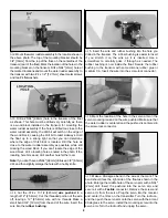
Note: Make sure the ventral fin is perpendicular to the
bottom of the fuselage.
❏
5. Remove the ventral fin assembly from the fuselage.
Solidly glue the ventral fin to the mounting base.
Most models are less stable with floats installed. The airflow
across the model is considerably different and the weight of
the floats is well below the CG, causing a pendulum effect
when the model is turned or rolled. In addition, the total
weight of the model is considerably higher. For these
reasons the model will not fly as you have become
accustomed to in the past.
For the first few flights with the floats installed, we
recommend that you balance the model for a somewhat
more nose heavy condition. This will increase the stability of
the model until you become accustomed to the changed
handling characteristics of the model. Remember that the
model is heavier and you must increase the takeoff and
landing speeds accordingly.
❏
1. Place a mark 1/4" forward of the mark you made before
you installed the floats. This will give a balance point 1/4"
more nose heavy.
❏
2. With the model assembled and the fuel tank empty,
balance the model at the new balance point. It is likely that
you will need about two ounces of lead to accomplish this.
Note: The added lead required to balance the model can be
added to the firewall or to the front of the floats. We
recommend that you add it to the top front of the floats,
though this is a bit unsightly. In the future when you remove
the floats and install the normal landing gear (and vice
versa), you won’t need to be concerned with removing or
adding weight – or forget to do so.
Before setting the model in the water, be sure the water
rudder on the float is extended. A reliable, slow idle is a
must. First flight attempts with floats should be reserved for
relatively calm days when the water is not very choppy.
Practice taxiing around in the water to learn the handling
characteristics, and see if you have built in enough throw on
the water rudder. Make adjustments if required. During
taxiing, hold “up” elevator to keep the nose of the aircraft
high and the propeller out of the water spray.
Always takeoff into the wind. Gently add throttle and
gradually release some of the up elevator as the speed
increases and the aircraft lifts “on the step” of the floats. Just
like the model takes off on the ground, when it has enough
speed it will lift into the air – don’t force it off. If the surface
of the water is very smooth, it may take a bit more elevator
to break the aircraft free of the surface tension of the water.
Continue a gradual, conservative climb out until you are at
an altitude where you are comfortable making the downwind
turn. Remember, the aircraft is heavier and has more drag
than you are used to. Many modelers snap roll into the water
on takeoff because they do not gain enough speed to allow
for the added weight and drag.
Learn the flight characteristics of the model with the added
weight and drag of the floats. The aerobatic response of the
model will be considerably different with the floats installed.
While the model should be perfectly capable of loops, rolls,
stall turns and inverted flight – these maneuvers will require
a much different pilot technique to do well.
Landing approach is the same on water as it is on land. Touch
down slowly to avoid bouncing the aircraft off the water and
back into the air. There is nothing that compares to a slow,
smooth touchdown on the water. “Crabbing” or “Slipping” is a
great technique used to bleed off excess airspeed during an
approach. This is done by applying a balance of rudder and
opposite aileron to make the aircraft fly “sideways”. The path of
the aircraft is “down the runway” while the nose is pointing off
to one side. Just before the floats contact the water, release the
rudder and opposite aileron.
Although it is difficult to do, the model can contact the water at
such an angle as to allow the tips of the floats to “catch” the tops
of any waves, thus flipping the model immediately. Avoid letting
the floats contact the water at anything but a level attitude; and
slightly nose high if there is much wave action.
Be considerate of others at the lake and enjoy your Great
Planes ARF Sport Floats.
FLYING
More than any other factor, the C.G. (balance point) can
have the greatest effect on how a model flies, and may
determine whether or not your first flight will be
successful. If you value this model and wish to enjoy it for
many flights, DO NOT OVERLOOK THIS IMPORTANT
PROCEDURE. A model that is not properly balanced will
be unstable and possibly unflyable.
Balance the Model
15


