❏
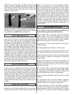
9. Trim the covering from the main landing gear slots on
the bottom of the wing. Apply a small amount of thin CA
along the slot to insure it is fuelproofed.
❏
10. Insert the main landing gear in the landing gear
slots. Position the four
nylon landing gear straps
over the
landing gear and mark the mounting hole locations.
❏
11. Drill a 3/32" [2.4mm] pilot hole at each mark.
❏
12. Attach the landing gear straps to the wing with
#4 x 1/2"
sheet metal screws.
❏
1. Position the
engine mount template
(found on page 21
of this instruction manual) on the firewall. Align the centerlines
of the template with the embossed marks on the firewall.
The marks on the firewall are off center to allow for the
built-in right thrust of the firewall.
❏
2. Mark the engine mount bolt holes and drill a 7/32"
[5.5mm] hole through the firewall at each mark.
❏
3. Insert an
8-32 blind nut
into each hole from the
backside of the firewall. Use an
8-32 x 1" socket head cap
screw
and
#8 flat washer
to seat the blind nuts in the back
of the firewall.
❏
4. Cut the “spreader bar” from the supplied Great Planes
adjustable engine mount.
Use a hobby knife to remove
any flashing left over from the molding process so that the
halves fit together without any binding.
❏
5. Temporarily install the engine mount on the firewall with
four 8-32 x 1" socket head cap screws,
#8 lock washers
and #8 flat washers. Do not tighten the screws all the way
so you can adjust the mount.
❏
6. Place your engine on the mount and adjust the halves
to fit the engine. Position the mount so the molded-in “tick
marks” are equally spaced on the horizontal off set line on
the firewall. When the engine mount is adjusted and
positioned, tighten the mounting screws.
❏
7. Position the engine on the mount so the drive washer
(or the back of the spinner) is 6-1/4" [158.7mm] away from
the firewall.
Use a Great Planes Dead Center
™
Hole
Locator
to mark the engine mounting holes.
❏
8. Drill a 7/64" [2.8mm] hole at each mark. Mount the
engine to the engine mount with four
#6 x 1" sheet metal
screws. Hint:
The screws will be easier to install if you first
rub the threads on a bar of soap.
Note:
On some engines the carburetor can be rotated so
that the needle valve points towards the top of the plane.
ENGINE INSTALLATION
11


