❏
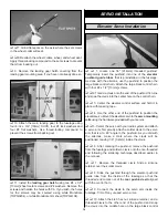
3. With the aileron centered, rotate the joiner rod straight up
to meet the bottom of the top wing aileron. Attach a nylon
control horn on the bottom of the top wing aileron.
❏
4. Adjust the clevis on both ends of the rod until both
ailerons are centered with the rod connecting them in place.
Tighten the 4-40 hex nuts and apply thread-locking
compound to prevent the hex nuts from loosening.
❏
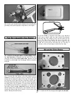
1. Use 6-minute epoxy and glue the included pilot figure
in the cockpit if desired.
❏
2. Apply the instrument panel decal.
❏
3. Trim the clear canopy along the marked trim lines.
❏
4. Attach the canopy to the fuselage using four #2 x 3/8"
[9.5mm] screws and #2 washers as shown. You may also
permanently mount the canopy using R/C Canopy Glue.
❏
1. Make all servo connections to the receiver as required
for your choice of radio setup.
❏
2. Wrap the receiver and receiver battery in 1/4" [6.4mm]
foam and secure it to the servo tray as shown using the
included hook and loop material.
❏
3. Install a switch and charge jack on the side of the fuselage.
1. Use scissors or a sharp hobby knife to cut the decals from
the sheet.
2. Be certain the model is clean and free from oily fingerprints
and dust. Prepare a dishpan or small bucket with a mixture of
liquid dish soap and warm water–about one teaspoon of soap
per gallon of water. Submerse the decal in the soap and water
and peel off the paper backing. Note: Even though the decals
have a “sticky-back” and are not the water transfer type,
submersing them in soap and water allows accurate
positioning and reduces air bubbles underneath.
3. Position the decal on the model where desired. Holding the
decal down, use a paper towel to wipe most of the water away.
4. Use a piece of soft balsa or something similar to
squeegee remaining water from under the decal. Apply the
rest of the decals the same way.
❏
1. Turn on the transmitter and receiver and center the
trims. If necessary, remove the servo arms from the servos
and reposition them so they are centered. Reinstall the
screws that hold on the servo arms.
❏
2. With the transmitter and receiver still on, check all the
control surfaces to see if they are centered. If necessary, adjust
the clevises on the pushrods to center the control surfaces.
❏
3. Make certain that the control surfaces and the carburetor
respond in the correct direction as shown in the diagram. If
CARBURETOR WIDE OPEN
RUDDER MOVES RIGHT
LEFT AILERON MOVES DOWN
RIGHT AILERON MOVES UP
ELEVATOR MOVES UP
4-CHANNEL
TRANSMITTER
(STANDARD MODE 2)
4-CHANNEL RADIO SETUP
TRANSMITTER
4-CHANNEL
TRANSMITTER
4-CHANNEL
TRANSMITTER
4-CHANNEL
Check the Control Directions
GET THE MODEL READY TO FLY
Apply the Decals
Mount the Receiver & Battery
Install the Pilot & Canopy
FINAL DETAILS
25


