GREAT PLANES ElectriCub Instruction Manual Download Page 46

The best place to fly your ElectriCub is at an AMA chartered
club field. Ask the AMA or your local hobby shop dealer if
there is a club in your area and join. Club fields are set up for
R/C flying and that makes your outing safer and more
enjoyable. The AMA also can tell you the name of a club in
your area. We recommend that you join AMA and a local club
so you can have a safe place to fly and have insurance to
cover you in case of a flying accident. The AMA address and
telephone number are in the front of this manual.

If a club and flying site are not available, find a large, grassy
area at least 6 miles away from houses, buildings and
streets and any other R/C radio operation like R/C boats
and R/C cars. A schoolyard may look inviting but is too close
to people, power lines and possible radio interference.

Inspect your radio installation and confirm that all the control
surfaces respond correctly to the transmitter inputs. The
motor operation must also be checked by confirming that
the motor reaches full power and the prop is rotating in the
correct direction. Make sure all screws remain tight, that the
hinges are secure and that the prop is on tight.

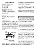
Whenever you go to the flying field, check the operational
range of the radio before the first flight of the day. First,
make sure no one else is on your frequency (channel). With
your transmitter on, you should be able to walk at least 100
feet away from the model and still have control. While you
work the controls, have a helper stand by your model and
tell you what the control surfaces are doing. Repeat this test
with the motor running at various speeds with a helper
holding the model. If the control surfaces are not always
responding correctly, do not fly! Find and correct the
problem first. Look for loose servo connections or corrosion,
loose bolts that may cause vibration, a defective on/off
switch, low battery voltage or a defective receiver battery, a
damaged receiver antenna, or a receiver crystal that may
have been damaged from a previous crash. If the radio
appears to only be affected when the motor is running, try
moving your receiver and receiver antenna farther away
from the motor battery and motor. Also, installing a couple
more capacitors on the motor may help. The capacitors
should be soldered from the terminals to the motor case
and from one terminal to the other.

Read and abide by the following Academy of Model
Aeronautics Official Safety Code:

General
1. I will not fly my model aircraft in sanctioned events, air

shows, or model flying demonstrations until it has been
proven to be airworthy by having been previously
successfully flight tested.

2. I will not fly my model aircraft higher than approximately

400 feet within 3 miles of an airport without notifying the
airport operator. I will give right of way to and avoid flying
in the proximity of full-scale aircraft. Where necessary an
observer shall be used to supervise flying to avoid having
models fly in the proximity of full-scale aircraft.

3. Where established, I will abide by the safely rules for the

flying site I use and I will not willfully and deliberately fly my
models in a careless, reckless and/or dangerous manner.

7. I will not fly my model unless it is identified with my name

and address or AMA number, on or in the model.

9. I will not operate models with pyrotechnics (any device

that explodes, burns, or propels a projectile or any kind).

Radio Control
1. I will have completed a successful radio equipment ground

check before the first flight of a new or repaired model

2. I will not fly my model aircraft in the presence of

spectators until I become a qualified flier, unless assisted
by an experienced helper.

3. I will perform my initial turn after takeoff away from the pit

or spectator areas and I will not thereafter fly over pit or
spectator areas, unless beyond my control.

4. I will operate my model using only radio control

frequencies currently allowed by the Federal
Communications Commission.

Caution  (THIS APPLIES TO ALL R/C AIRPLANES): If, while
flying, you notice any unusual sounds, such as a low-pitched
“buzz,” this may indicate control surface “flutter.” Because flutter
can quickly destroy components or your airplane, any time you
detect flutter you must immediately cut the throttle and land the
airplane! Check all servo grommets for deterioration (this may
indicate which surface fluttered) and make sure all pushrod
linkages are slop-free. If it fluttered once, it will probably flutter
again under similar circumstances unless you can eliminate the
slop or flexing in the linkages. Here are some things which can
result in flutter: Excessive hinge gap; Not mounting control horns
solidly; Sloppy fit of clevis pin in horn; elasticity present in flexible
plastic pushrods; Side-play of pushrod in guide tube caused by
tight bends; Sloppy fit of control rods in servo horns; Insufficient
glue used when gluing in torque rods; Excessive flexing of
aileron, caused by using too soft balsa; Excessive “play” or
“backlash” in servo gears; and insecure servo mounting.

FLYING

AMA SAFETY CODE (excerpts)

Range Check Your Radio

Ground Check the Model

Find a Safe Place to Fly

46

Summary of Contents for ElectriCub

Page 1: ...bility shall be assumed nor accepted for any damage resulting from the use by the user of the final user assembled product By the act of using the user assembled product the user accepts all resulting...

Page 2: ...STALL THE WING STRUTS 43 SET THE CONTROL THROWS 44 PROPER CARE OF YOUR MOTOR 44 PERFORMANCE TIPS 45 PREFLIGHT 45 Charge the Radio Batteries 45 Balance the Propeller 45 Find a Safe Place to Fly 46 Grou...

Page 3: ...o will be able to check out your construction and help you with your first flights We do know that once you have flown the ElectriCub you will want to keep it in your vehicle for that quick flight dur...

Page 4: ...h marginal performance that the climb out was very shallow and flight times were short Generally a high performance high power motor like the Great Planes S 600 direct drive motor will give the Electr...

Page 5: ...t HCAR0456 Builder s triangle HCAR0480 10 24 Tap and Drill set Masking tape TOPR8018 Panel line pen TOPQ2510 CG Machine GPMR2400 Accu Throw Deflection Meter GPMR2405 CA Applicator tips HCAR3780 CA Deb...

Page 6: ...Plan Protector to prevent glue from sticking to the plan 5 When instructed to test fit parts this means DO NOT USE GLUE until you are satisfied that everything fits properly THEN glue the parts toget...

Page 7: ...7 NOT USED NOT USED NOT USED DIE CUT PATTERNS...

Page 8: ...2 frame pieces a 3 16 x 3 8 x 30 balsa stick and the small 3 16 x 3 8 x 5 8 hardwood tailgear support 7 From the 3 16 x 3 16 x 24 balsa stick cut and glue the rudder ribs to the frame 8 Remove the rud...

Page 9: ...From the 3 16 x 3 16 x 24 balsa stick cut and glue the elevator ribs to the frame 9 Repeat steps 7 and 8 to build the second elevator half 10 Remove the elevators from your building board Inspect glu...

Page 10: ...permanently join the elevators 16 Lay the elevators and stab over the plan and lightly mark the hinge locations on the LE of the elevators and the TE of the stab Repeat the process to mark the hinge...

Page 11: ...ide up over the left wing panel plan so your progress matches the photos 1 Set aside two of the hardest and straightest 1 4 x 1 4 x 13 balsa sticks for use later to make pushrods 2 The shaped and notc...

Page 12: ...onto the main spar and into the notches in the trailing edge 9 Carefully insert the W 4 ribs into the notches in the leading edge Note Do not be concerned if the ribs do not line up exactly with the...

Page 13: ...ion The wing strut plates must be flat on the table flush with the bottom of the wing 16 From the 1 16 x 3 x 30 balsa sheet cut and glue vertical grain shear webs to the spars in the locations shown o...

Page 14: ...board 4 Assemble the die cut 1 8 ply wing tip jig and wing tip jig feet 5 Trial fit the wing halves together with one wing half flat on your building board and the wing tip jig under the tip rib of th...

Page 15: ...e wing tip on the end of the wing LE The TE of the wing tip should rest on the building table Sand off the end of W 6 until it just touches the inside edge of the wing tip 5 With the wing tip centered...

Page 16: ...f the notches on the bottom of the wing s TE Cut notches in the wing TE at the marks Test fit the center TE s with the torque rods installed checking that the notches align and are large enough to all...

Page 17: ...64 hole in the aileron for the torque rod Use the Great Planes Groove Tube or a sharpened brass tube to cut a groove for the torque rod in the LE of the aileron 11 Test fit the aileron on the wing to...

Page 18: ...t the TE and working toward the LE Then glue the tape on the top of the wing from the front edge of the wing plate to the LE Cut off the excess tape 5 Use a sanding bar to carefully feather the edges...

Page 19: ...With wax paper or Plan Protector positioned over the fuse plan pin the die cut 1 8 balsa forward lower fuselage FLF forward center fuselage FCF and upper fuselage FTF in position over the plan and gl...

Page 20: ...one right side 9 To provide right thrust in the firewall trim 3 32 off the front of the right fuselage side 10 Align and glue the die cut 1 8 balsa wing saddle doublers to the inside of both fuse sid...

Page 21: ...oth sides at the bottom of the die cut 1 8 plywood former F 2A Make sure the sticks are flush with the end of the tabs 2 From the leftover 1 8 x 3 8 balsa stick cut two pieces the full width of the di...

Page 22: ...t deck base 9 Trial fit former F 4 between the longerons at the former location lines the cross braces face aft Note that the sides of F 4 and the cross braces will have to be sanded to a slight taper...

Page 23: ...alsa battery bench seat to the battery bench supports 20 Position the fuse upside down on your building board Check that the tail post is perpendicular to the building board when viewed from the rear...

Page 24: ...t the firewall until the epoxy sets 29 Glue the die cut 1 8 balsa former F 1C to the front deck base 30 Trial fit the die cut 1 16 balsa top front sheet sanding as necessary Glue the front sheet to th...

Page 25: ...nt of the landing gear plate 36 Glue the die cut 1 32 x 5 8 x 1 1 2 plywood hatch plate to the balsa strip on the aft end of the battery hatch The hatch plate should extend about 1 8 past the aft edge...

Page 26: ...ie cut 1 8 balsa former F 3A to the rear edges of the upper fuse sides and the aft deck base 43 Glue the die cut 1 8 balsa rear wing saddle into the slots in the wing saddle doublers flush with the to...

Page 27: ...en the upper and middle longerons 1 Fill any small gaps in the fuselage with balsa filler 2 Use a sanding bar to sand the fuse sides and bottom smooth Sand the top front sheeting and chin plate flush...

Page 28: ...lly align it with the fuselage Use a tape measure to measure the distance from the corner of the aileron bay to the center of the tail post Then measure the distance from the other aileron bay and che...

Page 29: ...ng the centerline of the stab with the centerline of the fuse From a few feet behind the fuselage view the stabilizer checking that the stabilizer is parallel with the wing If not remove the stabilize...

Page 30: ...ls in the center notches of F 3A F 4A F 5A and F 6A Sand the aft end of the dowel at an angle to match the angle of the fin LE Glue the dowel in place Then cut off the forward end of the dowel flush w...

Page 31: ...joint between the outside dowel stringers and former F 3A 1 Turn the fuse upside down and position the 1 8 wire main landing gear on the 3 16 ply landing gear plate as shown on the plan Tack glue it i...

Page 32: ...ith a flux ring sand the raised area of the die cut 1 8 plywood motor mount sides flat 1 Drill a 1 8 hole at each of the punch marks on the die cut 1 8 plywood motor mount back and motor mount front 2...

Page 33: ...to cut out the propeller shaft hole and the vent holes in the front of the cowl Also cut out the cooling air exit hole on the bottom of the cowl 2 There are three small indentations near the rear edg...

Page 34: ...er pilot holes in the ends of the struts where shown for the mounting screws Note The struts will be mounted to the wing and fuse after the plane is covered Note The ElectriCub was designed to use min...

Page 35: ...ou should not be able to start the motor with the throttle stick In order for this safety feature to be effective you should always keep the toggle switch in the off position until you are ready to fl...

Page 36: ...e 9 Sand the end of the pushrod to a rounded shape 10 Wrap kite string or strong thread not included around the wire and balsa pushrod Then apply medium CA on the string 11 Make a 90 degree bend on on...

Page 37: ...as most of the finish is done with Top Flite MonoKote covering The only painting required is the cowl windshield frame dummy engine and hubcaps The technique we will describe here is how the model pi...

Page 38: ...may make a small wood block 1 4 high by gluing together pieces of leftover wood Keep this block handy while twisting and heating to check your progress Depending on what type of covering you have used...

Page 39: ...y Install the rudder with its hinges Repeat the gluing technique described previously and allow the epoxy to cure It is best to leave a very slight hinge gap rather than closing it up tight to help pr...

Page 40: ...gear and the aft strap attaches to the fuse 2 Reinstall the motor and cowl 3 Glue the dummy engines on the cowl so the cylinder heads line up with the prop shaft 4 Lightly sand a strip approximately 1...

Page 41: ...the front surface of the battery bench back Install the second hook strip on the bottom of the F 2 opening on top of the 1 4 x 1 4 balsa cross braces 5 Peel the backing from one of the fuzzy strips an...

Page 42: ...he left thus opposing the turn Adverse yaw is common in trainer type airplanes having flat bottom wings and is most noticeable at slow speeds and high angles of attack such as during takeoffs and when...

Page 43: ...rvo tray to the servo tray rails 1 Switch on your transmitter then the receiver Center the elevator and rudder servos Be sure the trim levers on your transmitter are centered 2 Center the elevator The...

Page 44: ...r more is not always better 1 The recommended Great Planes S 600 motor for direct drive and T 600r motor for gear drive require Break in by running the motor without the propeller for at least hour Th...

Page 45: ...ce 12 or 13 gauge wire This type of wire is normally multi strand 600 to 700 strands The larger the wire the less resistance in the wire 4 The standard Tamiya battery connectors supplied with your swi...

Page 46: ...y model aircraft in sanctioned events air shows or model flying demonstrations until it has been proven to be airworthy by having been previously successfully flight tested 2 I will not fly my model a...

Page 47: ...el to climb at a shallow angle do not yank the model off the ground into a steep climb We recommend that you take it easy with your ElectriCub for the first several flights gradually getting acquainte...

Page 48: ...2 View Use the 2 view or photocopy it and use the copy to design your trim scheme Printed in USA...

Reviews: