


34
❏
5. Cut out the dummy engines and exhaust pipes. Test fit
them on the cowl. The cylinder heads should line up with the
prop shaft of the real motor. Trim and sand as required for a
good fit. We waited until after the cowl and dummy engines
were painted before gluing them together.
❏
6. Since you are cutting out plastic parts, cut out the two
hub caps also. Test fit them on your 2" main wheels (not
included). When satisfied with their fit, set them aside until
after they are painted.
Note: The wing struts are optional (for scale like appearance)
and are not required for flying. They do, however, add
strength to the wing and do not seem to noticeably reduce
the performance.
❏
1. Sand the 3/32" x 1/4" x 16-1/4" hardwood sticks to an
airfoil shape as shown on the wing plan.
❏
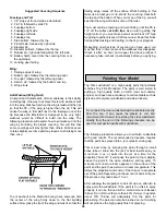
2. Working over the wing strut drawing on the wing plan,
make two sets of struts as shown. Note that where the
struts join you must cut one of the struts off at an angle
before gluing them together.
❏
3. Reinforce the ends of the struts by wrapping small
pieces of fiberglass around the struts and applying CA
glue. Sand the struts smooth.
❏
4. Drill 1/16" diameter pilot holes in the ends of the struts
where shown for the mounting screws.
Note: The struts will be mounted to the wing and fuse after
the plane is covered.
Note: The ElectriCub was designed to use mini servos on
all control surfaces. If you are installing an electronic speed
control, the throttle servo, receiver battery (if the speed
control has BEC and auto cutoff) and the toggle switch can
be omitted.
❏
1. Prepare the servos by installing the rubber grommets
and brass eyelets into each servo.
❏
2. Place the servos into the die-cut 1/8" plywood servo
tray and position them so they do not touch the sides of the
openings. Mark the servo mounting holes on the servo tray.
Remove the servos and drill 1/16" pilot holes at the marks.
Mount the servos to the servo tray using the mounting
screws provided with the servos.
❏
Note: If an electronic speed control is used, assemble the
speed control tray and mount it in the top opening in former
F-2A. The speed control can be held in place with a piece
of Velcro
®
applied to the top of the tray and the bottom of the
speed control.
❏
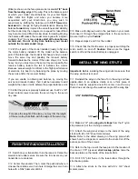
3. Mount the receiver switch on the side of the fuse. We found
a good place for the switch is just behind former F-2A along the
joint between the bottom fuse side and middle fuse side.
Mount the Servos
RADIO INSTALLATION
Construct the Wing Struts