background image

20

Do not run the motor in an area of loose gravel or sand; the 
propeller may throw such material in your face or eyes.

Keep your face and body as well as all spectators away from 
the plane of rotation of the propeller as you run the motor.

Keep these items away from the prop: loose clothing, shirt 
sleeves, ties, scarfs, long hair or loose objects such as 
pencils or screwdrivers that may fall out of shirt or jacket 
pockets into the prop.

The motor gets hot! Do not touch it during or right after 
operation. 

When working on your plane, remove the propeller if the 
motor battery will be connected. 

Always remove the motor battery from the plane when 
charging.

Follow the charging instructions included with your charger 
for charging LiPo batteries. LiPo batteries can cause serious 
damage if misused.

AMA SAFETY CODE (excerpts)

Read and abide by the following excerpts from the Academy 
of Model Aeronautics Safety Code. For the complete Safety 
Code refer to Model Aviation magazine, the AMA web site or 
the Code that came with your AMA license.

General

1) I will not fl y my model aircraft in sanctioned events, air shows, 
or model fl ying demonstrations until it has been proven to be 
airworthy by having been previously, successfully fl ight tested.

2) I will not fl y my model aircraft higher than approximately 
400 feet within 3 miles of an airport without notifying the 
airport operator. I will give right-of-way and avoid fl ying in the 
proximity of full-scale aircraft. Where necessary, an observer 
shall be utilized to supervise fl ying to avoid having models fl y 
in the proximity of full-scale aircraft.

3) Where established, I will abide by the safety rules for the 
fl ying site I use, and I will not willfully and deliberately fl y my 
models in a careless, reckless and/or dangerous manner.

5) I will not fl y my model unless it is identifi ed with my name 
and address or AMA number, on or in the model. Note: This 
does not apply to models while being fl own indoors.

7) I will not operate models with pyrotechnics (any device 
that explodes, burns, or propels a projectile of any kind).

Radio Control

1) I will have completed a successful radio equipment ground 
check before the fi rst fl ight of a new or repaired model.

2) I will not fl y my model aircraft in the presence of spectators 
until I become a qualifi ed fl ier, unless assisted by an 
experienced helper.

3) At all fl ying sites a straight or curved line(s) must be 
established in front of which all fl ying takes place with the 
other side for spectators. Only personnel involved with fl ying 
the aircraft are allowed at or in the front of the fl ight line. 
Intentional fl ying behind the fl ight line is prohibited.

4) I will operate my model using only radio control frequencies 
currently allowed by the Federal Communications Commission.

5)  I will not knowingly operate my model within three 
miles of any pre-existing fl ying site except in accordance 
with the frequency sharing agreement listed
 (in the 
complete AMA Safety Code).

9) Under no circumstances may a pilot or other person 
touch a powered model in fl ight; nor should any part of the 
model other than the landing gear, intentionally touch 
the ground, except while landing
.

CHECK LIST

During the last few moments of preparation your mind may 
be elsewhere anticipating the excitement of the fi rst  fl ight. 
Because of this, you may be more likely to overlook certain 
checks and procedures that should be performed before the 
model is fl own. To help avoid this, a check list is provided to 
make sure these important areas are not overlooked. Many 
are covered in the instruction manual, so where appropriate, 
refer to the manual for complete instructions. Be sure to 
check the items off as they are completed.

 1.   Check the C.G. according to the measurements 

provided in the manual.

 2.   Be certain the battery and receiver are securely 

mounted in the fuselage. Simply stuffi ng them into 
place with foam rubber is not suffi cient.

 3.   Extend your receiver antenna and make sure it has a 

strain relief inside the fuselage to keep tension off the 
solder joint inside the receiver.

 4.   Balance your model laterally as explained in

the instructions.

 5.   Use threadlocking compound to secure critical 

fasteners such as the motor screws, wheel collar 
SHCS and screw-lock pushrod connectors, etc.

 6.   Add a drop of oil to the axles so the wheels will

turn freely.

 7.  Make sure all hinges are securely glued in place.

Summary of Contents for EDGE 540 T Performance Series

Page 1: ...t Planes reserves the right to change or modify this warranty without notice In that Great Planes has no control over the final assembly or material used for final assembly no liability shall be assum...

Page 2: ...d ARF The Great Planes Edge 540T EP ARF flies much like the giant size Edge s but in a much less expensive package Now you can practice for IMAC competition without risking your larger more expensive...

Page 3: ...rs of which may cause eye skin and respiratory tract irritation Never blow into a part wheel pant cowl to remove fiberglass dust as the dust will blow back into your eyes Always wear safety goggles a...

Page 4: ...discharge w balance plug GPMP0623 FlightPower EVO25 LiPo 2170mAh 11 1V 25C FPWP0327 FlightPower EVO25 LiPo 2500mAh 11 1V 25C FPWP0333 APC 13 x 8E Propeller APCQ3080 3D Setup Great Planes Power Series...

Page 5: ...ERING REPLACEMENT PARTS Replacement parts for the Great Planes Edge 540T EP ARF are available using the order numbers in the Replacement Parts List that follows The fastest most economical service can...

Page 6: ...the part names exactly as they are written in the Kit Contents list Great Planes Product Support 3002 N Apollo Drive Suite 1 Champaign IL 61822 Telephone 217 398 8970 ext 5 Fax 217 398 7721 E mail ai...

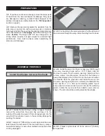
Page 7: ...to the wing Test fit your aileron servo in the servo bay Enlarge the opening if required 2 Install a 12 305mm servo extension onto the servo lead Secure the extension to the lead with tape a piece of...

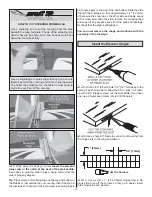
Page 8: ...ne clevis retainer over the clevis With the aileron servo and the aileron centered mark the aileron pushrod where it crosses the aileron servo arm Make a 90 bend at the mark Cut the pushrod 3 8 9 5mm...

Page 9: ...at steps 1 to 4 for the left main landing gear Install the Tail Gear 1 Glue the nylon tail gear bushing in the hole in the aft bottom of the fuselage 2 Insert the tail gear wire through the aluminum t...

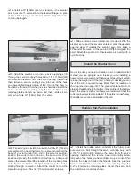
Page 10: ...humb screws Be careful putting pressure on the wing and fuselage The wings may be tight the first time they are slid on the tube 2 Center the horizontal stabilizer in the slot in the fuselage Stand ba...

Page 11: ...uselage so that part of the bare wood is showing Apply 30 minute epoxy to the wood top and bottom Slide the stab through the fuselage so that approximately 1 2 12 7mm of bare wood is showing on the ot...

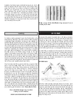
Page 12: ...es with thin CA Install the Motor The Edge 540T EP has been designed to use the Great Planes RimFire 42 50 800 Out runner Brushless motor If you will be installing a different motor you may need to mo...

Page 13: ...cone clevis retainer over the clevis With the elevator servo and the elevator centered mark the elevator pushrod where it crosses the elevator servo arm Make a 90 bend at the mark Cut the pushrod 3 8...

Page 14: ...Measure up 3 4 19mm from the bottom of the rudder and make a mark Measure in from the leading edge 1 4 6 4mm and make a mark Drill a 3 32 2 4mm hole through the rudder perpendicular to the centerline...

Page 15: ...tion in the Tail 1 Cut the covering away from the upper opening on the right side in the rear of the fuselage for the rudder servo 2 Install a 16 406mm servo extension on the rudder servo Secure the e...

Page 16: ...slot on the other side of the tray 9 Attach a strip of sticky backed hook material to the center of the battery tray The loop material can be attached to the battery Apply the Decals The box photograp...

Page 17: ...AILERONS 3 4 19mm 15 up 3 4 19mm 15 down LOW RATE ELEVATOR 1 2 13mm 8 up 1 2 13mm 8 down RUDDER 2 51mm 17 left 2 51mm 17 right AILERONS 1 2 13mm 10 up 1 2 13mm 10 down 3D RATE ELEVATOR 2 1 2 64mm 42 u...

Page 18: ...t flights Later you may wish to experiment by shifting the C G up to 3 16 5mm forward or 3 16 5mm back to change the flying characteristics Moving the C G forward may improve the smoothness and stabil...

Page 19: ...ay be flying with batteries that are only partially charged Balance Propellers Carefully balance your propeller and spare propellers before you fly An unbalanced prop can be the single most significan...

Page 20: ...I will have completed a successful radio equipment ground check before the first flight of a new or repaired model 2 I will not fly my model aircraft in the presence of spectators until I become a qua...

Page 21: ...e runway Hold up elevator to keep the tail wheel on the ground If necessary adjust the tail wheel so the model will roll straight down the runway If you need to calm your nerves before the maiden flig...

Page 22: ...prove your skills though it is never a bad idea but more importantly so you do not surprise yourself by impulsively attempting a maneuver and suddenly finding that you ve run out of time altitude or a...

Page 23: ...d a little bit of power back in You will have to adjust the throttle as needed but make your adjustments smooth Some right aileron may be needed to keep the model from torque rolling Use the rudder an...

Page 24: ...ive housing optimizes cooling allowing RimFire motors to produce 50 more performance power than out runners of similar size Prop adapter motor mount and hardware are included The installed gold plated...

Reviews: