GREAT PLANES Easy Sport 40 Instruction Manual Download Page 20

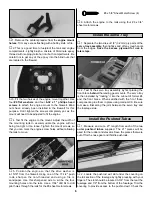
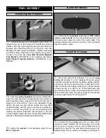
suit your own personal tastes. Roughen the bottom 1/8" of
the canopy edge, as well as the area on the wing fairing that
the canopy contacts. Be careful not to scratch any areas that
may be visible when the canopy is installed. Glue the
canopy in position with 6-minute epoxy or RC-56 glue. Finish
the canopy by painting the frame lines using fuelproof paint
or striping tape. 

Note

: Always test your paint on a small sample of the

canopy to make sure that it doesn’t attack or deform the
the canopy material.

Note: 

This section is 

VERY IMPORTANT 

and must 

NOT

be omitted! A model that is not properly balanced will be

unstable and possibly unflyable.
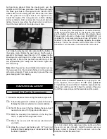
1. Accurately mark the balance point on the 

bottom

of the

wing on both sides of the fuselage. The balance point is
located 

4-1/8" back from the leading edge

. This is the

balance point at which your model should be balanced for
your first flights. Later, you may wish to experiment by shifting
up to 

1/4" forward or aft 

to change the flight characteristics.

Moving the balance 

forward

may improve the smoothness

and arrow-like tracking, but it may then require more speed
for takeoff and make it more difficult to slow down for landing.
Moving the balance point 

aft

makes the model more agile

with a lighter and snappier “feel” and often improves knife
edge capabilities. In any case, 

please start at the location

we recommend and do not at any time balance your
model outside the recommended range

.

2. With the wing attached to the fuselage, all parts of the

model installed (ready to fly) and an 

empty

fuel tank, hold the

model at the marked balance point with the stabilizer level.

3. Lift the model. If the tail drops when you lift, the

model is “tail heavy” and you must add weight* to the nose.
If the nose drops, it is “nose heavy” and you must add
weight* to the tail to balance.

Note

: Nose weight may be added by using a Heavy Spinner

nut (1/4"-28 GPMQ4640)(5/16"-24 GPMQ4641) or by gluing
weights to the firewall. Tail weight may be added by using
Great Planes (GPMQ4485) “stick-on” lead weights. Later, if
the balance proves to be O.K., you can open the bottom of
the fuse and glue these permanently in position.

*If possible, first attempt to balance the model by changing
the position of the receiver battery and receiver. If you are
unable to obtain good balance by doing so, then it will be
necessary to add weight to the nose or tail to achieve the
proper balance point.

4-1/8"

Balance Your Model

Note

: Throws are measures at the widest part of the

elevators, rudder and ailerons.

We recommend the following control surface throws:

High rates

Low rates

ELEVATOR

1/2" UP

3/8" UP

1/2" DOWN

3/8" DOWN

RUDDER

1-1/4" RIGHT

1" RIGHT

1-1/4" LEFT

1" LEFT

AILERONS

7/16" UP

5/16" UP

7/16" DOWN

5/16" DOWN

CARBURETOR WIDE OPEN

NOSE WHEEL TURNS RIGHT

RUDDER MOVES RIGHT

LEFT AILERON MOVES DOWN

RIGHT AILERON MOVES UP

ELEVATOR MOVES UP

4-CHANNEL

TRANSMITTER

(STANDARD MODE 2)

4-CHANNEL RADIO SETUP

TRANSMITTER

4-CHANNEL

TRANSMITTER

4-CHANNEL

TRANSMITTER

4-CHANNEL

Control Surface Throws

20

Summary of Contents for Easy Sport 40

Page 1: ...final assembly no liability shall be assumed nor accepted for any damage resulting from the use by the user of the final user assembled product By the act of using the user assembled product the user...

Page 2: ...ry to yourself or spectators and damage property If this is your first sport model we recommend that you get help from an experienced knowledgeable modeler with your first flights You ll learn faster...

Page 3: ...lanes brand TOP is the Top Flite brand and HCA is the Hobbico brand 4 Channel Radio with 4 Servos Engine See Engine Selection above Propellers see engine instructions for sizes 18 Silicone fuel tubing...

Page 4: ...n Abbreviations Optional Supplies and Tools 4 Futaba 4NBF Conquest 4 channel Radio Flexibility and convenience make the Futaba Conquest FM radio systems a good choice for experienced fliers FUTJ39 Gre...

Page 5: ...15 Wing Tape 16 6 32 x 1 Screws 17 Wheel Collars 18 6 32 x 3 4 Sheet Metal Screws 19 Nylon Landing Gear Straps 20 6 Flat Washers 21 Silicone Clevis Retainers 22 Nylon Steering Arm 23 Nylon Control Ho...

Page 6: ...e the die cut ply forward and aft root ribs to both wing roots Be sure that they are aligned with the top and bottom of the wing When installing the forward root rib it should be noted that the tab is...

Page 7: ...he paper towel can also be used to remove any fingerprints or epoxy residue that may have been left behind 1 Glue the aileron servo tray and uprights into the wing using 6 minute epoxy 1 Lay the wing...

Page 8: ...o scribe the four mounting holes onto the rails Use a 7 64 drill bit to drill pilot holes through the rails for the 6 sheet metal screws 6 Attach the engine to the rails using four 6 x 3 4 sheet metal...

Page 9: ...right hole in the firewall This will be used for the throttle pushrod Leave about 1 4 of the tube exposed in front of the firewall Glue the pushrod tube to both sides of the firewall using medium CA 6...

Page 10: ...te A small piece of music wire or a cut down hex wrench can be used to extend the needle if it does not reach through the fuse side 3 Fit the hatch in position By measurement determine where to drill...

Page 11: ...ed to the fuselage use a 5 32 drill bit to drill through the wing and into the wing hold down plate When drilling be sure that the drill bit remains square to the wing bolt plate in all directions 5 E...

Page 12: ...sing 6 minute epoxy glue the joiner wire into position Make sure the joiner wire is fully seated in the elevator halves before the epoxy cures Use weights to keep the elevator halves from moving 1 Loc...

Page 13: ...he proper position of the stabilizer 7 Attach a piece of string with a T pin to the top center of the firewall The string should be long enough to reach to the horizontal stabilizer Align the stabiliz...

Page 14: ...horizontal stabilizer when viewing from the rear Use masking tape to hold the vertical fin in this position Check this alignment several times as the epoxy cures 1 Work the hinges into the slits in t...

Page 15: ...thin coat of thin CA should be applied This can be done by applying the CA then using a piece of waxed paper or plastic spread the glue until the wood has been completely covered by the CA 4 Measure...

Page 16: ...servos following the radio manufacturer s recommendations B Test fit the servos in the tray Enlarge the openings if needed to create a 1 32 gap around the servo C Mark the mounting hole locations on t...

Page 17: ...ntrol horn then clip the clevis to the top hole of the horn Make a second assembly exactly the same as the first Clevis placement will be adjusted on the horn for proper control throw later Note Make...

Page 18: ...rottle movement and to prevent the servo from binding at its end points 8 Cut four 1 4 bushings and slide them onto the remaining 17 1 2 pushrod 3 apart starting 2 1 2 from the non threaded end Bend t...

Page 19: ...is position allows easier flip starting 3 Attach the spinner to the backplate using the two M3 x 15 screws 1 Install the three wheels using the six 5 32 wheel collars and set screws Grind or file a fl...

Page 20: ...e your model outside the recommended range 2 With the wing attached to the fuselage all parts of the model installed ready to fly and an empty fuel tank hold the model at the marked balance point with...

Page 21: ...the controls have a helper stand by your model and tell you what the control surfaces are doing Repeat this test with the engine running at various speeds with a helper holding the model If the contro...

Page 22: ...ce any sluggishness in the way your Easy Sport handles it is probably a result of not enough speed in which case you should install a propeller with increased pitch When it s time to land fly a normal...

Page 23: ...which gases other than air enter their internal combustion engine s nor will I operate models with extremely hazardous fuels such as those containing tetranitromethane or hydrazine 9 I will not operat...

Page 24: ...FLIGHT LOG DATE COMMENTS Started Construction Finished Construction First Flight...

Reviews: