


both parts are aligned. Slide the steering arm over the
straight end of the nose gear wire. Insert the wire through
the lower gear hole in the engine mount. Install a 5/32"
wheel collar onto the nose gear wire above the hole. Slide
the nose gear into the upper hole in the engine mount.
Adjust the height of the nose gear wire until the fuselage
sits level. Install a 6-32 set screw into the wheel collar and
tighten the set screw while the wheel collar is resting on
top of the lower portion of the engine mount hole.
❏
2. Slide the steering arm into contact with the bottom of
the engine mount. Rotate the gear wire so that the axle is
parallel to the firewall. Insert the 6-32 x 1/4"
screw
into the
steering arm and thread it in a few turns. Position the
steering arm in front of the pushrod hole with the tip of the
arm approximately 5/8" away from the firewall. Tighten the
screw securely.
Note
: After the gear has been installed and tested, remove
the nose gear strut. File or grind a flat spot on the gear wire
at the screw location. This is necessary to prevent the nose
gear steering arm from slipping.
1. Follow this sequence for mounting the radio components:
❏
A. Install rubber grommets and brass eyelets in the servos
following the radio manufacturer’s recommendations.
❏
B. Test fit the servos in the tray. Enlarge the openings if
needed to create a 1/32" gap around the servo.
❏
C. Mark the mounting hole locations on the tray, then
drill 1/16" pilot holes through each mark.
❏
D. Mount the servos with the screws provided with
your radio.
❏
E. Wrap the receiver and battery with 1/4" foam (not
included). Use masking tape or rubber bands to hold
the foam in position.
❏
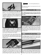
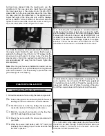
1. Following the manufacturer’s recommendations,
install and connect three servos, the receiver, the switch
and the battery as shown in the photo. We added a Great
Planes Switch Mount & Charge Jack (#GPMM1000, not
included) for convenience and ease of use at the field. It is
installed in the side of the fuselage opposite the engine
exhaust. Center the elevator and rudder trims on the
transmitter. Turn the radio on and center the servo arms.
❏
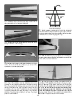
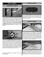
2.Assemble the
swivel clevises
by snapping the two
parts together, then thread a
17-1/2" wire pushrod
13 revolutions into each of them. Thread the swivels onto the
torque rods until they are 3/4" above the surface of the wing.
Cut off the excess torque rod that extends past the swivel.
❏
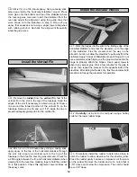
3. Cut a notch in the aileron servo tray so the wire from
the servo can pass through. Install the aileron servo as
shown in step 4. Connect it to the receiver, turn on the
radio, then center the servo horn.
Install the Radio Components
RADIO INSTALLATION
16