


❏
4. Center the ailerons, then mark the pushrods at the
point where they meet the holes on the servo arm. Make a
90 degree bend down in the wires at this mark.
❏
5. Cut off the excess wire 3/8" above the bend. Enlarge
the servo horn holes with a 5/64" drill bit. Insert the bent
wire pushrods into the servo horn from the upper side, then
secure them with Nylon FasLink
™
Pushrod Keepers.
❏
1. Slide a
silicone retainer
over the “hex” end of a
nylon clevis
. Thread the clevis 13 revolutions onto the
threaded end of a
37" wire pushrod
. Cut six 1/4"
bushings
from the 6-1/2" plastic inner pushrod tube
provided in the kit. Slide the bushings on the wire pushrod,
spacing them about 3" apart.
Check the pushrod to be
certain that the bushings won’t pop out of the ends and
cause the pushrods to stick.
Put a drop of thin CA on the
pushrod wire at each bushing to hold them in place. Trim
the backing plate from a
nylon control horn
, then clip the
clevis to the top hole of the horn. Make a second assembly
exactly the same as the first.
Clevis placement will be
adjusted on the horn for proper control throw later
.
Note
: Make sure the CA has
fully cured before
proceeding
to the next step.
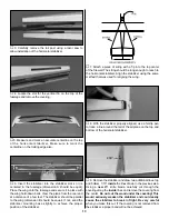
❏
2. Insert the pushrods into the tubes in the fuselage.
Hold the horn against the control surface (see sketch
above for correct alignment).
Note
: Be sure that the control
horn positions match those in the photo. The pushrod
should not be bent and should slide easily in the tube.
Mark the location for the horn screws on the control
surface. Drill the 3/32" horn screw holes through the control
surface. Mount the horn tightly in place with two
2-56
machine screws
and the
horn backing plate
. Repeat for
the other control surface as shown.
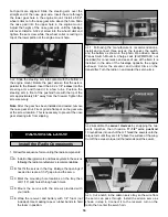
❏ ❏
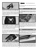
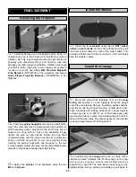
3. Install a
Screw-Lock Pushrod Connector
with
the
4-40 x 1/8" cap screw
on the throttle and rudder servo
horns. Snap the
nylon retainer
onto the pushrod
connector post beneath the servo horn. Use the photo for
the correct positioning of the connectors.
RIGHT
WRONG
Install the Pushrods & Control Horns
17