C. Apply a small drop of solder flux to the joint.
D. Heat the area to be soldered. Apply solder to the heated
area. The metal must get hot enough to melt the solder and
the solder must flow into the joint. Do not melt the solder by
touching it to the soldering iron.
E. Do not move the parts until the solder has cooled.
F. Clean off the excess flux with alcohol.
G. Test the joint by pulling on it.
H. Apply a light coat of oil to the joint to prevent rust.
❏
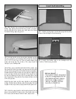
9. Once the solder clevis has cooled, install a silicone
clevis keeper on the clevis. Remove the 4-40 metal clevis
and 4-40 nut and insert the rudder pushrod in the rudder
outer pushrod tube. Connect the clevis to the rudder servo
arm. Reinstall the 4-40 nut and clevis and connect it to the
rudder control horn.
❏
10. Install the elevator servo and attach a solder clevis to
one of the elevator pushrods using the same method as
used for the rudder.
❏
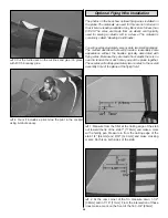
11. Insert the elevator pushrod in the elevator outer pushrod
tube. Center the other elevator. Bend the pushrod to the same
angle as the first elevator pushrod where the two meet.
❏
12. Cut the second elevator pushrod 1/4" [6.4mm] behind
the solder clevis.
❏
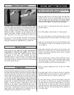
13. Remove the first elevator pushrod and install two
3/16" wheel collars on the pushrod. Reinstall the first
elevator pushrod in the outer pushrod tube. Slide the two
wheel collars over the second pushrod. Secure the wheel
collars to the two elevator pushrods with two 6-32 x 1/4"
[6.4mm] socket head cap screws. Make sure to use
threadlock on the two screws. Make sure the cap head
screws do not hit the fuselage former.
❏
14. Reinstall the clevis on the first elevator pushrod and
reattach it to the elevator control horn.
❏
15. Wrap the receiver in 1/4" [6.4mm] foam. Use #64
rubber bands to hold the receiver to the radio tray. Route the
receiver antenna out the antenna tube installed in the top of
the fuselage. Plug the servos into the receiver.
❏
16. We installed the radio switch and the battery charge
jack in the front of the cockpit. Place the pilot in the cockpit
as your guide for positioning the switch and charge jack.
❏
17. Connect the battery to the radio switch and secure
the ends of the leads with heat-shrink tubing, tape or some
other method for securing the leads.
20


