23
❏
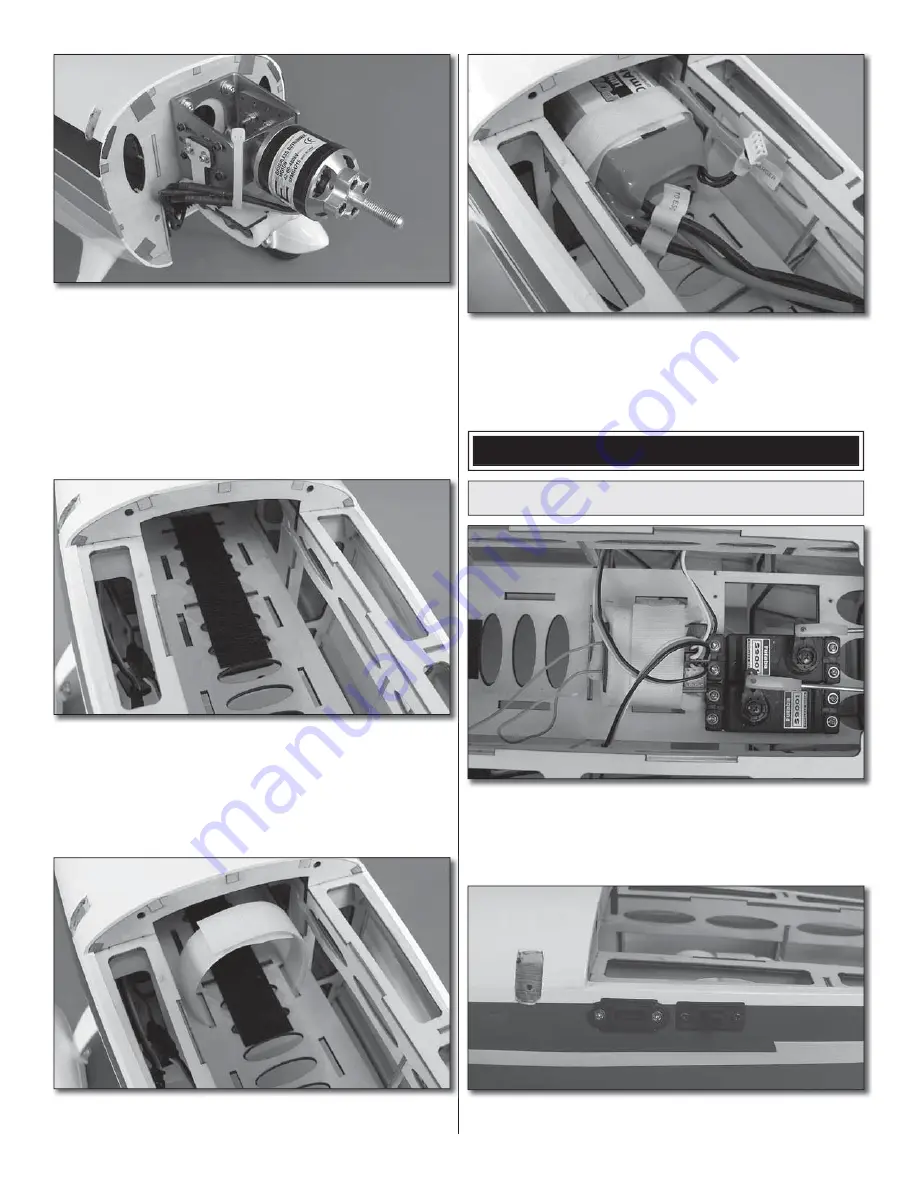
10. Attach a 6" [152mm] servo extension to the receiver
battery using a piece of heat shrink tubing to secure the
connection. Connect the ESC to the motor and route the
receiver and battery wires through the fi rewall toward the
servos. Now would be a good time to test the operation
of the motor using your radio system. The motor should
rotate counter-clockwise when looking at it from the front. If
it rotates the wrong direction simply swap two of the three
motor leads. Use a tie strap (not included) or tape to secure
the motor lead wires to the motor mounting box.
❏
11. Apply a thin coat of epoxy down the center of the
battery tray. This will improve the adhesion of the hook and
loop material. When the epoxy has completely cured, attach
a piece of the hook side from some self-adhesive hook and
loop material (not included) to the battery tray. The loop
side should be attached to your battery pack (use additional
pieces to join LiPo packs together for a series confi guration).
❏
12. Make a hook and loop strap approximately 10" [254mm]
long and feed the strap through the slots in the battery tray.
❏
13. Test fi t your batteries onto the tray. Adjust the length
of the strap if necessary. When you check the balance of the
plane, the exact position of the batteries on the tray will be
determined.
FINISH THE MODEL
Install the Receiver and Battery
❏
1. Make a strap from the included hook and loop material
to fi t your receiver. Cut a piece of foam rubber (not included)
to fi t your receiver and strap the receiver to the radio tray as
shown. Connect the rudder, elevator and throttle servos to
the receiver (or ESC if applicable).
❏
2. Mount your switch harness and charge jack to the
fuselage side in the location that you prefer.
Summary of Contents for Christen Eagle .46
Page 36: ......


