


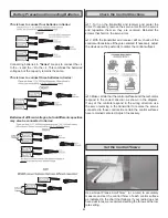


Note: The throws are measured at the widest part of the
elevators, rudder and ailerons. If you are using a ruler to
set your control surface throws, the defl ection distance is
measured as the height from the center TE of the control
surface when moved from the neutral position as shown
in the sketch. Defl ection in degrees is also provided for an
alternative measuring method.
These are the recommended control surface throws:
High Rate
Low Rate
ELEVATOR: 1/2" [13mm] 21 deg up
3/8" [9.5mm] 16 deg up
1/2" [13mm] 21 deg down
3/8" [9.5mm] 16 deg down
RUDDER:
1-1/4" [32mm] 34 deg right 5/8" [16mm] 17 deg right
1-1/4" [32mm] 34 deg left 5/8" [16mm] 17 deg left
AILERONS:
1" [25mm] 24 deg up
7/16" [11mm] 10 deg up
1" [25mm] 24 deg down
7/16" [11mm] 10 deg down
FLAPS:
(Full) 9/16" [14mm] 24 deg
(1/2) 5/16" [8mm] 13 deg
IMPORTANT: The Cherokee .40 ARF has been
extensively fl own and tested to arrive at the throws at
which it fl ies best. Flying your model at these throws will
provide you with the greatest chance for successful fi rst
fl ights. If, after you have become accustomed to the way
the Cherokee .40 ARF fl ies, you would like to change the
throws to suit your taste, that is fi ne. However, too much
control throw could make the model diffi cult to control, so
remember, “more is not always better.”
Balance the Model (C.G.)
More than any other factor, the C.G. (balance point) can
have the greatest effect on how a model fl ies, and may
determine whether or not your fi rst fl ight will be successful.
If you value this model and wish to enjoy it for many fl ights,
DO NOT OVERLOOK THIS IMPORTANT PROCEDURE.
A model that is not properly balanced will be unstable and
possibly unfl yable.
At this stage the model should be in ready-to-fl y condition
with all of the systems in place including the engine or
brushless motor, landing gear, and the radio system (and
battery pack if applicable).
❏
1. Use a felt-tip pen or 1/8" [3mm]-wide tape to accurately
mark the C.G. on the top of the wing on both sides of the
fuselage. The C.G. is located 3-1/16" [78mm] back from the
LE of the wing.
This is where your model should balance for the fi rst
fl ights. Later, you may wish to experiment by shifting the
C.G. up to 7/16" [11mm] forward or 7/16" [11mm] back to
change the fl ying characteristics. Moving the C.G. forward
may improve the smoothness and stability, but the model
may then require more speed for takeoff and make it more
diffi cult to slow for landing. Moving the C.G. aft makes
the model more maneuverable, but could also cause it to
become too diffi cult to control. In any case, start at the
recommended balance point and do not at any time
balance the model outside the specifi ed range.
❏
2. With the wing attached to the fuselage, all parts of the
model installed (ready to fl y) and an empty fuel tank, place
the model upside-down on a Great Planes C.G. Machine, or
lift it upside-down at the balance point you marked.
❏
3. If the tail drops, the model is “tail heavy” and the battery
pack and/or receiver must be shifted forward or weight must
be added to the nose to balance. If the nose drops, the model
is “nose heavy” and the battery pack and/or receiver must be
shifted aft or weight must be added to the tail to balance. If
possible, relocate the battery pack and receiver to minimize
or eliminate any additional ballast required. If additional
weight is required, nose weight may be easily added by
using a “spinner weight” (GPMQ4645 for the 1 oz. [28g]
weight, or GPMQ4646 for the 2 oz. [57g] weight). If spinner
weight is not practical or is not enough, use Great Planes
(GPMQ4485) “stick-on” lead. A good place to add stick-
on nose weight is to the fi rewall (don’t attach weight to the
cowl–it is not intended to support weight). Begin by placing
incrementally increasing amounts of weight on the bottom
of the fuselage over the fi rewall until the model balances.
Once you have determined the amount of weight required, it
can be permanently attached. If required, tail weight may be
added by cutting open the bottom of the fuselage and gluing
it permanently inside.
Note: Do not rely upon the adhesive on the back of the lead
weight to permanently hold it in place. Over time, fuel and
exhaust residue may soften the adhesive and cause the
weight to fall off. Use #2 sheet metal screws, RTV silicone or
epoxy to permanently hold the weight in place.
❏
4. IMPORTANT: If you found it necessary to add any weight,
recheck the C.G. after the weight has been installed.
24