GREAT PLANES Cherokee .40 ARF Instruction Manual Download Page 14

14

❏ 

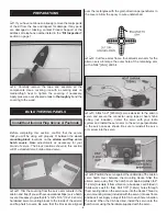
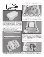
2. Fit the stopper assembly into the tank with the vent 

line pointing toward the top of the tank, but not touching. 
The fuel tubing and clunks (fuel pickup) on the carb and fi ll 
lines should almost reach the back of the tank but not touch. 
The clunks must be able to move freely inside the tank when 
assembled. Adjust the length of the fuel tubing accordingly. 
When satisfi ed, tighten the 3 x 25mm screw in the stopper to 
secure it in place (do not overtighten). Mark the side of the 
tank that must face up when installed in the plane, and we 
also suggest marking the tubes in the stopper.

❏ 

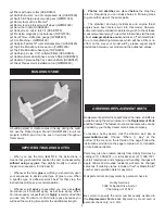
3. Make two 12" [305mm] long hook and loop straps from 

the included hook and loop material by overlapping the mating 

ends of each side by approximately 2" [51mm]. Insert the 
straps into the slots in the plywood fuel tank tray as shown.
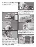
❏ 

4. Fit the fuel tank tray into the fuselage by inserting the tab 

at the forward end of the tray into the slot in the fi rewall. Press 
the tray down onto the receiving tabs in the fuselage former 
and cross brace. Drill two 1/16" [1.6mm] holes through the 
tray and into the hardwood mounting blocks. Secure the tray 
in place using two #2 x 1/2" [13mm] screws and two #2 fl at 
washers, being sure to harden the screw holes with thin CA.

❏ 

5. Cut a piece of 1/4" [6mm] foam rubber (not included) to 

fi t the fuel tank. Lay the foam rubber onto the fuel tank tray (it 
can be glued into place). Insert the neck of the tank through 
the hole in the fi rewall as far as it will go (being sure that the 
right side of the tank is facing up). Use the hook and loop 
straps to secure the tank in place.
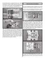
❏ 

6. Attach a 6" [152mm] piece of fuel tubing to each of the 

tubes in the fuel tank stopper.

❏ 

7. Using four 6-32 x 3/4" [19mm] SHCS, four #6 fl at 

washers, four #6 lock washers, and threadlocking compound, 
attach the engine mount side-mounted to the fi rewall so that 

Summary of Contents for Cherokee .40 ARF

Page 1: ...resulting from the use by the user of the final user assembled product By the act of using the user assembled product the user accepts all resulting liability If the buyer is not prepared to accept t...

Page 2: ...or the veteran pilot who just appreciates the rich history of the Cherokee For the latest technical updates or manual corrections to the Cherokee 40 ARF visit the Great Planes web site at www greatpla...

Page 3: ...ormance of your completed model and no representations are expressed or implied as to the performance or safety of your completed model Remember Take your time and follow the instructions to end up wi...

Page 4: ...rs for both are provided below Great Planes PolyCharge4 DC only 4 output LiPo charger GPMM3015 or Great Planes ElectriFly Triton2 DC comp peak charger GPMM3153 ADDITIONAL ITEMS REQUIRED Required Hardw...

Page 5: ...you will need the working time and or the additional strength Photos and sketches are placed before the step they refer to Frequently you can study photos in following steps to get another view of the...

Page 6: ...3243 Horizontal Stabilizer Elevator GPMA3244 Canopy Hatch GPMA3245 Wheel Pants GPMA3246 Landing Gear GPMA3247 Cowl GPMA3248 Wing Tube GPMA3249 Decal Sheet COMMON ABBREVIATIONS Stab Horizontal Stabiliz...

Page 7: ...re written in the Kit Contents list Great Planes Product Support 3002 N Apollo Drive Suite 1 Champaign IL 61822 Telephone 217 398 8970 ext 5 Fax 217 398 7721 E mail airsupport greatplanes com 1 Cowl 2...

Page 8: ...m hardwood servo mounting blocks to the inside of the aileron and flap hatch covers Be sure that the blocks are aligned over the rectangles with the grain direction perpendicular to the covers Allow t...

Page 9: ...control horn 8 Position the control horn over the plywood plate in the aileron if you cannot see it hold the aileron at a shallow angle in good lighting or use a small pin to puncture the covering usi...

Page 10: ...the screw holes with thin CA 12 Install a control horn onto the flap using two 2 x 3 8 9 5mm screws Make note that these screws are shorter than the ones used for the aileron control horns As you did...

Page 11: ...the wood when cutting the covering 4 Wipe away the lines from the pen using a cloth dampened with alcohol and glue the strips into position BUILD THE FUSELAGE Install the Tail Surfaces 1 Place the hor...

Page 12: ...ter the rudder servo with your radio system and install the servo arm perpendicular to the servo case as shown with the outer drilled hole toward the center of the fuselage 2 Temporarily insert a 36 9...

Page 13: ...is on the elevator pushrod should attach to the outer hole in the elevator control horn Glow Engine Installation The Cherokee 40 ARF is designed to be flown with a 40 to 46 two stroke glow engine 56 f...

Page 14: ...n 4 Fit the fuel tank tray into the fuselage by inserting the tab at the forward end of the tray into the slot in the firewall Press the tray down onto the receiving tabs in the fuselage former and cr...

Page 15: ...ine to the mount using four 6 32 x 3 4 19mm SHCS four 6 flat washers and four 6 lock washers 9 Drill a 3 16 4 8mm hole in the firewall inline with throttle arm in the carburetor using a long drill bit...

Page 16: ...cess pushrod 1 4 6mm behind the screw lock pushrod connector Brushless Motor Installation If you have installed a glow engine skip this section as it only contains information relevant to installing a...

Page 17: ...ots in the plywood fuel tank tray as shown The fuel tank tray is also used as the battery tray for a brushless installation 5 Fit the fuel tank tray into the fuselage by inserting the tab at the forwa...

Page 18: ...install the wheel pants wheel collars and wheels onto the axles Thread a 6 32 x 1 4 6mm SHCS into each wheel collar with threadlocking compound and tighten the screws against the flat spots on the axl...

Page 19: ...nting holes onto the hardwood plate Drill 3 32 2 4mm holes at the marks you made Mount the steering block onto the hardwood plate using four 4 x 5 8 16mm self tapping screws being sure to harden the h...

Page 20: ...done so already cut the fuel line and vent line to muffler to the correct length and connect them to the engine The fill line should be left uncut and it can hang free from the bottom of the plane A f...

Page 21: ...e and align it with the colors on the fuselage When satisfied with the fit tape the cowl into position Measure 3 8 9 5mm forward from the aft end of the cowl at each mark you made on the masking tape...

Page 22: ...sors or a sharp hobby knife to cut the decals from the sheet 2 Be certain the model is clean and free from oily fingerprints and dust Prepare a dishpan or small bucket with a mixture of liquid dish so...

Page 23: ...vo arms 2 With the transmitter and receiver still on check all the control surfaces to see if they are centered If necessary adjust the clevises on the pushrods to center the control surfaces 3 Make c...

Page 24: ...ater you may wish to experiment by shifting the C G up to 7 16 11mm forward or 7 16 11mm back to change the flying characteristics Moving the C G forward may improve the smoothness and stability but t...

Page 25: ...Propellers Carefully balance your propeller and spare propellers before you fly An unbalanced prop can be the single most significant cause of vibration that can damage your model Not only will engine...

Page 26: ...re to follow all instructions could cause permanent damage to the battery and its surroundings and cause bodily harm ONLY use a LiPo approved charger NEVER use a NiCd NiMH peak charger NEVER charge in...

Page 27: ...nnectors etc 6 Add a drop of oil to the axles so the wheels will turn freely 7 Make sure all hinges are securely glued in place 8 Reinforce holes for wood screws with thin CA where appropriate servo m...

Page 28: ...utter is detected is to slow the model immediately by reducing power then land as soon as safely possible Identify which surface fluttered so the problem may be resolved by checking all the servo grom...

Reviews: