background image

26

CHOKE CONTROL

The choke can be controlled manually or with a servo.

Manual Choke Control


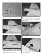
1. Assemble the choke pushrod.


2. Install the manual choke pushrod.

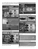
Servo Controlled Choke


1. Install the servo controlled choke pushrod following the 

same procedure used to install the throttle pushrod.

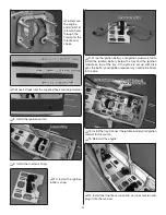
Assemble the Fuel Tank

❏ 

1. Clean both ends of the brass tubes with sandpaper.


2. Solder fuel line barbs onto one end of the brass tubes.


3. Insert the brass tubes in the fuel tank stopper and 

stopper plates.


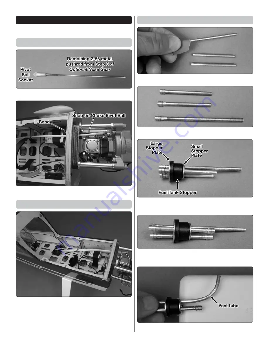
4. Solder the barbs on the other end of the two shorter 

brass tubes.


5. Bend the vent tube. The tube should not touch the tank.

Summary of Contents for Avistar 30cc ARF

Page 1: ...hat Great Planes has no control over the final assembly or material used for final assembly no liability shall be assumed nor accepted for any damage resulting from the use by the user of the final us...

Page 2: ...to the instructions Do not alter or modify the model as doing so may result in an unsafe or unflyable model In a few cases the instructions may differ slightly from the photos In those instances the w...

Page 3: ...pleted model REMEMBER Take your time and follow the instructions to end up with a well built model that is straight and true DECISIONS YOU MUST MAKE This is a partial list of items required to finish...

Page 4: ...n on cable clutter at the same time It uses digital serial data communication technology to transmit control signals between your receiver and servos A single S Bus cable can carry signals to as many...

Page 5: ...rvo Extension FUTM4140 TACM2700 2 1000mm S Bus Hub FUTM4196 Electric Motor Installation 1 S Bus Servo Hub Cable 300mm FUTM4195 1 16 Servo Extension FUTM4145 1 Y harness for elevator TACM2751 or FUTM41...

Page 6: ...HCAQ1050 Propeller and spare propellers suitable for your engine Dubro 813 Fuel Line Barbs DUBQ0670 Adhesives and Building Supplies This is the list of Adhesives and Building Supplies that are require...

Page 7: ...port 3002 N Apollo Drive Suite 1 Ph 217 398 8970 ext 5 Champaign IL 61822 Fax 217 398 7721 E mail airsupport greatplanes com Jet White TOPQ0204 Black TOPQ0208 Metallic Gold TOPQ0404 Sapphire Blue TOPQ...

Page 8: ...g panel KIT CONTENTS 1 Fuselage 2 Cowl 3 Left Wing Panel 4 Right Wing Panel 5 Horizontal Stabilizer 6 Vertical Stabilizer 7 Main Wheels 8 Main Gear 9 Main Wheel Pants 10 Tail Gear 11 Spinner 12 Fuel T...

Page 9: ...he covering from over the aileron servo opening 4 Route the servo lead or the decoder lead through the wing 5 Drill servo screw mounting hole 6 Install servo screws 7 Connect the servo to the aileron...

Page 10: ...10 9 Install the 4 40 threaded clevis 10 Attach clevis to control horn 11 Position control horn on aileron 12 Mount control horn 13 Install the solder clevis...

Page 11: ...ary Wipe off the flux residue with denatured alcohol Coat the joint with oil to prevent rust 14 Reinstall the aileron pushrods and slide the retainers over the clevises 15 Repeat steps 1 14 to install...

Page 12: ...ervo 7 Install the flap control horn following the same procedure used to install the aileron control horn 8 Install the flap servo in the right wing half Note that the servo arm is on the wing root s...

Page 13: ...t holes ASSEMBLE THE FUSELAGE Install the Tail 1 Slide both wing halves onto the wing tube Slide the wing halves together 2 Install the wing on the fuselage 3 Trim the covering 4 Temporarily install t...

Page 14: ...e parallel If they are not lightly sand the stabilizer slot 7 Use 30 minute epoxy to glue the stabilizer and fin in the fuselage Clean off any excess epoxy with denatured epoxy and paper towels Instal...

Page 15: ...f the plane is being built as the optional trike gear skip ahead to Install the Optional Trike Gear 6 Install the main landing gear on the fuselage Install the Tail Gear 1 Drill a 15 64 6mm hole in th...

Page 16: ...unting hole locations 7 Drill a 1 16 1 5mm hole at each mark 8 Apply 6 minute epoxy in the hole for the tail gear wire support Before the epoxy cures insert the support in the hole and the tail gear w...

Page 17: ...the front of the firewall Apply a drop of glue to each nut to hold it secure 5 Separate the top and bottom of the nylon nose gear bearing Install the nose gear bearing on the back side of the firewal...

Page 18: ...tion the wheel pant and mark the location of the nose gear wire on the wheel pant 10 Drill 1 16 1 6mm holes and attach the landing gear straps 11 Position a 5mm wheel collar under the nose gear bearin...

Page 19: ...arge recepticle Connect the receiver battery to the switch and the switch to the receiver 6 Insert a 4 40 x 48 metal pushrod into the middle pushrod tube 7 Install the rudder servo and plug it into th...

Page 20: ...sed for the aileron pushrods 12 Reinstall the rudder pushrod 13 Install the elevator pushrods following the same procedure used for the rudder Nose Gear Steering for optional nose gear 1 Trim and glue...

Page 21: ...ligns with the pushrod connector 8 Remove the rudder servo arm insert the steering pushrod in the pushrod connector and reinstall the servo arm 9 Center the nose wheel and tighten the screw Electric M...

Page 22: ...firewall 5 Install the RimFire 1 60 motor 6 Mount the ESC Connect the wires from the ESC to the motor wires 7 Attach the motor box to the firewall 8 Connect a 16 406mm servo extension to the ESC Plug...

Page 23: ...ill the firewall for your engine 2 Install the pivot ball on the throttle and choke arm 3 If installing one of the DLE engines glue the three 1 8 3 2mm plywood engine standoffs together Apply a thin c...

Page 24: ...strap 11 Wrap the ignition battery and ignition module in foam Install the ignition battery below the tray and the ignition module on top of the tray If the plane is set up with trike gear the batter...

Page 25: ...l Switch on the radio system and move the throttle stick to full throttle Rotate the throttle arm to full throttle 22 Slide the plywood outer pushrod support onto the outer pushrod 23 Thread the throt...

Page 26: ...ed choke pushrod following the same procedure used to install the throttle pushrod Assemble the Fuel Tank 1 Clean both ends of the brass tubes with sandpaper 2 Solder fuel line barbs onto one end of t...

Page 27: ...freely 7 Loosely install the fuel tank stopper screw 8 Secure the fuel tank stopper in the fuel tank Mark the top of the tank Install the Fuel Tank 1 Install and mark the fuel lines Vent Carb and Fil...

Page 28: ...DLE engines The O S GT33 requires the brass insert in the backplate The backplate fits on the RimFire 1 60 3 Drill 5 64 2mm pilot holes Attach the cowl using 4x1 2 12 7mm sheet metal screws and 4 flat...

Page 29: ...cket with a mixture of liquid dish soap and warm water about 1 2 teaspoon of soap per gallon of water Submerse one of the decals in the solution and peel off the paper backing NOTE Even though the dec...

Page 30: ...AILERON MOVES UP LEFT AILERON MOVES DOWN 4 CHANNEL RADIO SET UP STANDARD MODE 2 4 Make certain that the control surfaces and the carburetor respond in the correct direction as shown in the diagram If...

Page 31: ...the high rate settings These are the recommended control surface throws ELEVATOR HIGH RATE LOW RATE 3 4 19mm 21 Up 3 4 19mm 21 Down 1 2 13mm 14 Up 1 2 13mm 14 Down 3 4 19mm 17 Up 3 4 19mm 17 Down 1 2...

Page 32: ...fuse under the TE of the fin Do this several times 2 If one wing always drops when you lift the model it means that side is heavy Balance the airplane by adding weight to the other wing tip An airplan...

Page 33: ...e is done with a fast charger the batteries may not reach their full capacity and you may be flying with batteries that are only partially charged Ground Check and Range Check Make sure the engine idl...

Page 34: ...ve it unattended during charge or discharge ALWAYS KEEP OUT OF THE REACH OF CHILDREN NEVER charge the battery in the plane ALWAYS remove the battery from the plane after a crash Set it aside in a safe...

Page 35: ...der to counteract engine torque Gain as much speed as your runway and flying site will practically allow before gently applying up elevator lifting the model into the air At this moment it is likely t...

Page 36: ...upport 1 Tail gear wheel collar 1 Tail gear wheel collar set screw 7 Extra large control horns 3 Control horn back plates 3 Plywood engine mount spacers 2 10 x 30mm Wing dowels 1 8 x 30mm wing alignme...

Reviews: