


2018-07-30
401-805M
YP4425A
Preparation and Setup
20
Fertilizer Connection Types
Making Fertilizer Connections
Heights and Leveling
All frame sections must be at the correct height and level
to maintain even planting depth.
Periodic frame-leveling adjustments should not be
necessary. For problems with uneven depth, check
planter levelness and follow these procedures.
1.
Before making any adjustments be sure the lift
cylinders are re-phased and operating properly. If
not, see “
2.
3.
Unfold the planter fully (page 24).
Set Tongue Height
Planter must be unfolded for this procedure.
Set the initial tongue height, using 3-point or hydraulic
tongue cylinder. Distance is measured at top of tongue to
ground level.
•
For standard 3-point hitch:
Set depth stop to capture this working height.
If desired height cannot be attained with normal
range of hitch, swivel coupler weldment may be
relocated in tongue bolt holes.
Tractor 3-point control must be in Depth Control
mode, and not Draft Control mode.
•
For hydraulic tongue:
Note the scale reading on the tongue for this height.
[Re]set the tongue height to this value when planting.
Type
Description
2
2-section, planter manifold and pump:
Starter inlet only
3
3-section, cart manifold and pump:
Left, Center, Right inlets & Gauge line
PFC2000 tank cart, YP4425A Planter with Type 2 and Type 3 Manifolds, & Ground Drive Pump
Planter Inlet
Left Type 3
Center Type 3
Right Type 3
Type 2
Gauge Line
a
a. Gauge Line is supplied with PFC1600 or PFC2000 tank cart
PFC1600 or PFC2000 tank cart, YP4425A Planter with Type 3 Manifold (only)
Planter Inlet
Left Type 3
Center Type 3
Right Type 3
Gauge Line
L
C
R
S
G
L
C
R
G
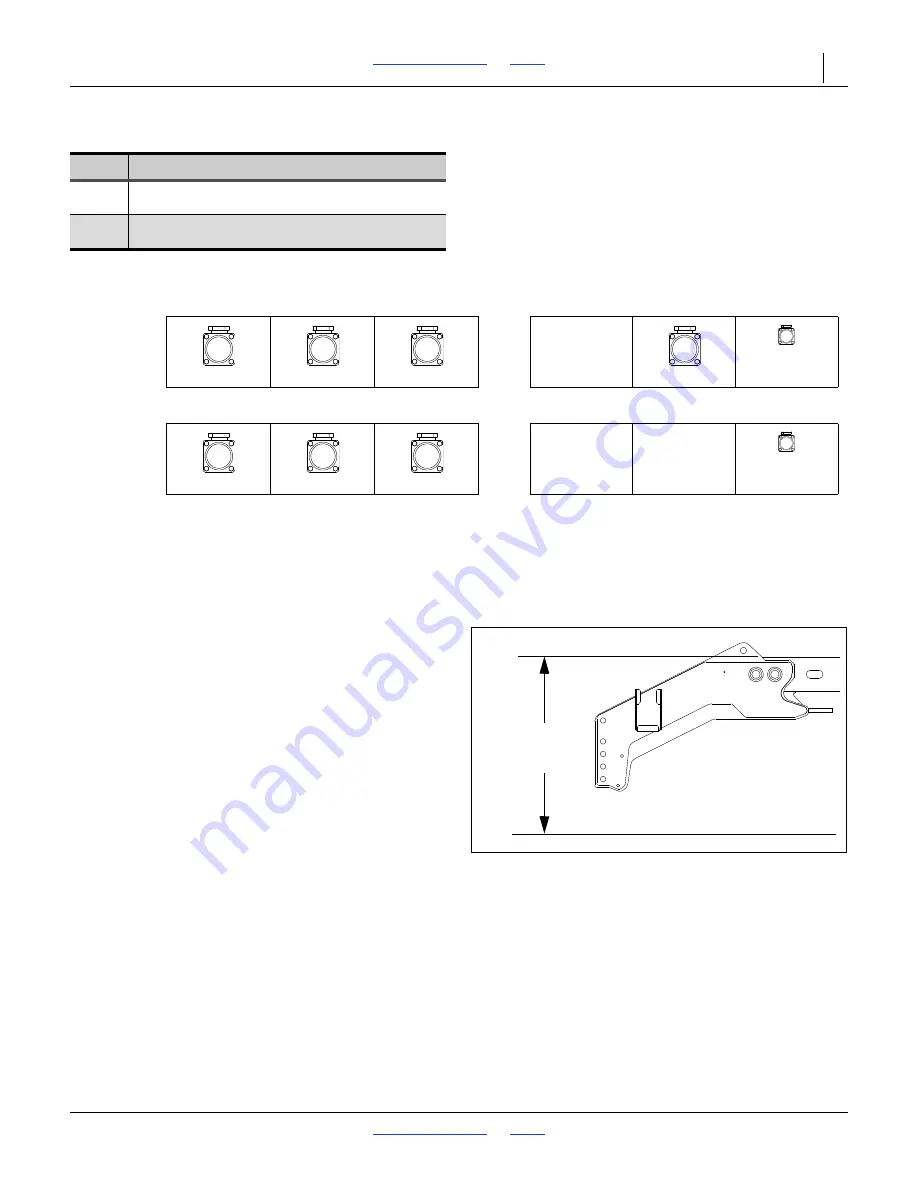
Figure 12
Initial Tongue Height
34087
Level frame in planting conditions.
Failure to do so may result in implement not
producing desired results.
41.5 inch
(105.4 cm)