background image

Manufacturing, Inc.

www.greatplainsmfg.com

© Copyright 2019

Printed 02/26/2019

166-207M

EN

Table of Contents

Index

Table of Contents

Index

ORIGINAL INSTRUCTIONS

Operator Manual

NTA907HD and NTA3007HD

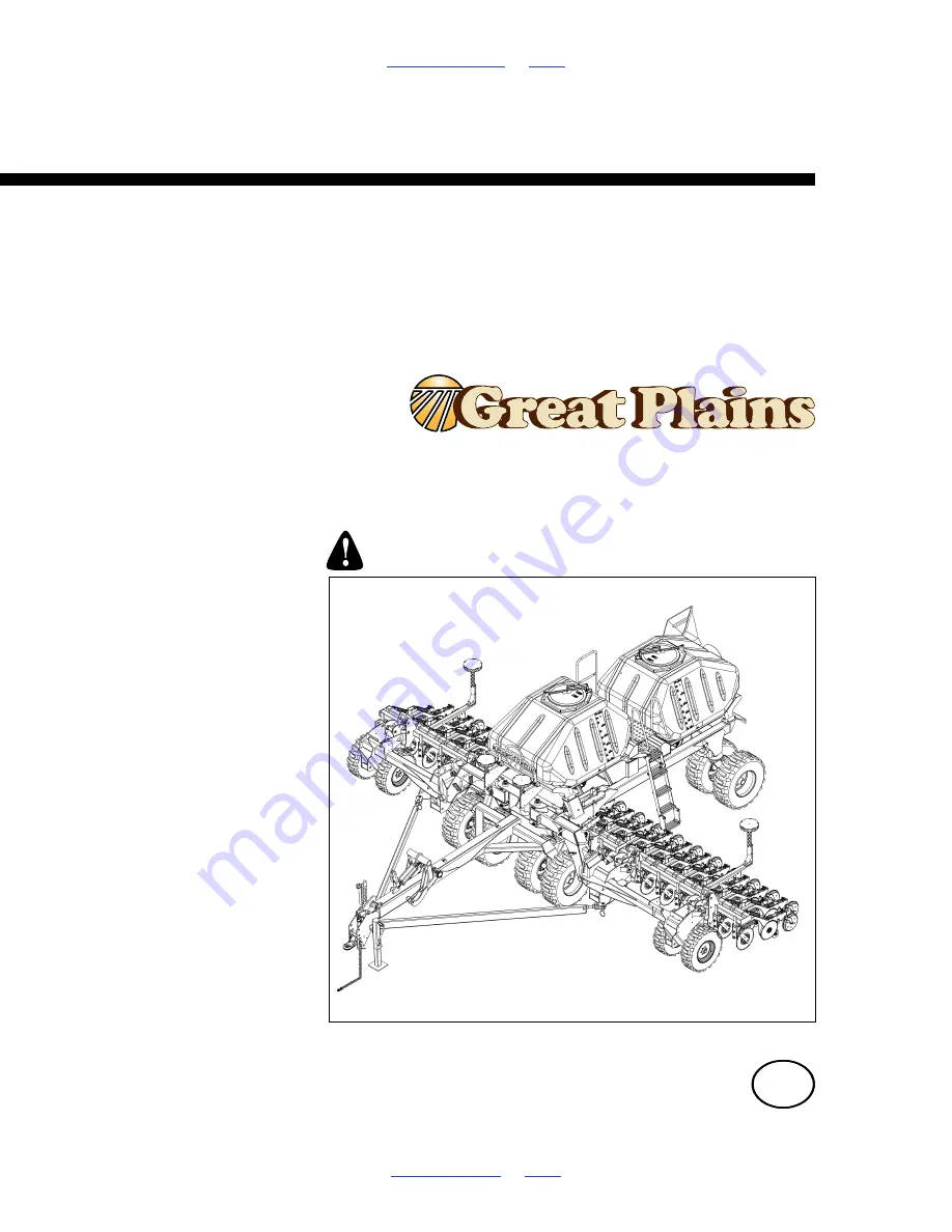
9m/30ft No-Till Heavy Duty Air Drill

Read the operator manual entirely. When you see this symbol, the subsequent 
instructions and warnings are serious - follow without exception. Your life and 
the lives of others depend on it!

Illustrations may show optional equipment not supplied with standard unit.

29423

Summary of Contents for NTA3007HD

Page 1: ...TRUCTIONS Operator Manual NTA907HD and NTA3007HD 9m 30ft No Till Heavy Duty Air Drill Read the operator manual entirely When you see this symbol the subsequent instructions and warnings are serious follow without exception Your life and the lives of others depend on it Illustrations may show optional equipment not supplied with standard unit 29423 ...

Page 2: ...Great Plains 166 207M 02 26 2019 Table of Contents Index ii 166 207M Table of Contents Index ...

Page 3: ...ered the weights and measurements are no longer accurate for your machine Update the record by adding the machine weight and measurements with the option s weight and measurements Dealer Contact Information Model Number Serial Number Machine Height Machine Length Machine Width Machine Weight Year of Construction Delivery Date First Operation Accessories Name Street City State Telephone Email Deale...

Page 4: ...2SF24 and 2SF30 ...

Page 5: ...raulic Motor Seals 19 Brake Hookup Option 20 Electrical Hookup 22 Heights and Leveling 22 Marker Setup 23 Operating Instructions 24 Pre Start Checklist 24 CFM Overview 24 Unfolding the Air Drill 25 Unfolding Summary of Steps 26 Unfolding Check Drill Configuration 26 Unfolding Release Transport Hook 26 Unfolding Release Transport Locks 27 Unfolding Tilt Down 28 Unfolding Check That Openers are Rais...

Page 6: ...Filter 116 Brake Maintenance Option 117 Brake Line Charge and Bleed 117 Air Brake Maintenance 119 Brake Drum and Liner Maintenance 119 Brake Shoe Replacement 121 Brake Drum Maintenance 125 Mounting Wheels 126 Test and Adjust Brakes 126 Leveling Drill 127 Section Alignment 127 Tool Bar Heights 128 Seed Flap Replacement 129 Marker Maintenance 130 Marker Shear Bolt 130 Marker Hydraulic Bleeding 130 M...

Page 7: ...situation which if not avoided will result in death or serious injury This signal word is limited to the most extreme situations typically for machine components that for functional purposes cannot be guarded WARNING indicates a potentially hazardous situation which if not avoided could result in death or serious injury and includes hazards that are exposed when guards are removed It may also be u...

Page 8: ...y should it separate from tractor draw bar Use a chain with a strength rating equal to or greater than the gross weight of towed machinery Attach chain to tractor draw bar support or other specified anchor location Allow only enough slack in chain to permit turning Replace chain if any links or end fittings are broken stretched or damaged Do not use safety chain for towing Avoid High Pressure Flui...

Page 9: ...fined Space With materials loaded or once used for hazardous fertilizers or seeds with hazardous treatments your hoppers may become permit required confined spaces under applicable statutes regulations insurance rules or business policy The vent tube structure in the hoppers has features to assist escape and is not for routine entry A hopper that is full or merely appears full can be an entrapment...

Page 10: ...ers Off Machinery Riders obstruct the operator s view Riders could be struck by foreign objects or thrown from the machine Never allow children to operate equipment Keep all bystanders away from machine during operation Transport Machinery Safely Maximum transport speed for implement is 30 kph or 20 mph Some rough terrains require a slower speed Sudden braking can cause a towed load to swerve and ...

Page 11: ...nnect battery ground cable before servicing or adjusting electrical systems Welding Disconnect battery ground Protect hydraulic lines Avoid fumes from heated paint Inspect all parts Make sure parts are in good condition and installed properly Remove buildup of grease oil or debris Remove all tools and unused parts from Air Drill before operation Safety At All Times Thoroughly read and understand t...

Page 12: ...new decals 1 Clean the area on which the decal is to be placed 2 Peel backing from decal Press firmly on surface being careful not to cause air bubbles under decal Reflector Slow Moving Vehicle SMV on mainframe below fan 1 total See Transport Safety Information on page 40 Reflectors Fluorescent Panels panels one each tongue draw bar panels and triangles one each corner rear mainframe 4 panels and ...

Page 13: ...ng gauge wheel mount on rear face each wing main tool bar on outside face mainframe sides ahead of ladder on outside face rear caster mount weldment 8 total See Transport Safety Information on page 40 Danger Electrocution Auger Option On auger tube near lower handles one total See Auger Safety Information on page 48 NTA907HD n a International models use 833 398C panels and 833 399C reflectors NTA3...

Page 14: ...ty Information on page 48 Danger Read Manual On side of tongue one total Danger Rotating Auger Option On auger tube near Missing Guard decal 1 total See Auger Safety Information on page 48 NTA907HD 848 408C NTA3007HD 29433 NTA907HD 848 410C NTA3007HD 818 633C 29424 NTA907HD 838 358C NTA3007HD 818 557C 818 557C Text in Spanish advises non English readers to seek translation 29424 29428 Si No Lee In...

Page 15: ...luid Large On side of tongue at hitch one total See Hydraulic Hose Hookup on page 19 See Hydraulic Maintenance Safety Information on page 111 NTA907HD 848 412C NTA3007HD 818 628C 29424 NTA907HD 848 400C NTA3007HD 848 400C 29424 NTA907HD 838 364C NTA3007HD 818 632C 29424 NTA907HD 838 359C NTA3007HD 818 437C 29428 29424 Wear proper hand and eye protection this type of injury If injured seek immediat...

Page 16: ...Down Force Safety Information on page 84 See Weight Transfer Safety Information on page 90 Warning Moving Chain On outside center face of main frame side tubes See Calibration Crank Safety Information on page 56 Warning Overhead Auger Option On outside face of auger arm on each end of auger tube 3 total See Auger Safety Information on page 48 On each side of inner marker arm 4 total See Marker Saf...

Page 17: ...on on page 34 See Down Force Safety Information on page 84 See Weight Transfer Safety Information on page 90 Warning Pinch Point Standard On outside faces of wing gauge wheel mounts 2 total See Unfolding Safety Information on page 25 See Lowering Raising Safety Information on page 32 See Folding Safety Information on page 34 Warning Pinch Point Auger Option On outside face of auger arm on auger tu...

Page 18: ... page 40 Warning Speed On rear main frame total See Transport Safety Information on page 40 Caution Read Operator Manual On side of tongue near hitch one total NTA907HD 838 365C NTA3007HD 818 798C 29433 NTA907HD n a see 848 398C 30kph NTA3007HD 818 188C 29424 818 188C Rev C Do Not exceed 20 mph maximum transport speed Loss of vehicle control and or machine can result To Prevent Serious Injury or D...

Page 19: ...uge wheel weldments 8 total See Unfolding Safety Information on page 25 See Folding Safety Information on page 34 See Down Force Safety Information on page 84 See Weight Transfer Safety Information on page 90 NTA3007HD 818 635C NTA3007HD 818 635C 29424 NTA907HD 838 360C NTA3007HD 818 437C 29424 29428 Wear proper hand and eye protection this type of injury If injured seek immediate medical help fro...

Page 20: ... See Transport Safety Information on page 40 Caution Tire Pressure and Torque On outside of each transport wheel tire 4 total See Transport Safety Information on page 40 Caution Towing On outside of each wing gauge wheel tire 4 total See Transport Safety Information on page 40 NTA907HD 848 406C NTA3007HD 838 092C 29424 NTA907HD 848 407C NTA3007HD 838 426C 29424 NTA907HD 838 358C NTA3007HD 848 394C...

Page 21: ...ill for use with attachments other than Great Plains options and accessories specified for use with the NTA907 3007HD Drill Document Family Using This Manual This manual will familiarize you with safety hitching operation adjustments troubleshooting and maintenance Read this manual and follow the recommendations to help ensure safe and efficient operation The information in this manual is current ...

Page 22: ...Model Number __________________________ Serial Number __________________________ Further Assistance Great Plains Manufacturing Inc and your Great Plains dealer want you to be satisfied with your new product If for any reason you do not understand any part of this manual or are otherwise dissatisfied please take the following actions first 1 Discuss the matter with your dealership service manager M...

Page 23: ... marker extension page 162 and speed Seasonal Setup On initial delivery use with a new tractor and seasonally check and as necessary complete these items before continuing to the routine setup items Bleed hydraulic system page 111 Wing leveling and alignment page 127 Speed sensor calibration DICKEY john Air Cart Control manual Blow out entire air system to remove condensation Check air flow at eac...

Page 24: ...atch your tractor draw bar height using crank of tongue jack on side of tongue The precise height is not critical as the NTA907 3007HD drill leveling is set at the mainframe and is independent of tongue level Hitch Failure Risk The hitch may be mounted inverted if necessary but always have two 2 bolts in two holes of both tongue and hitch 4 Securely attach safety chain to an anchor on a tractor ca...

Page 25: ... to plastic hose label The hose under an extended cylinder symbol feeds a cylinder base end The hose under a retracted cylinder symbol feeds a cylinder rod end For hydraulic fan and auger drive motors connect the hose under the retracted cylinder symbol to the pressure side of the motor Connect the hose under the extended cylinder symbol to the return side of the motor The fan motor further requir...

Page 26: ...and may not be engaged by any tractor Emergency Brake Both drill systems include an independent cable operated parking brake on the drill The tractor cannot engage or release the drill s parking brake system Braking Hazards Make sure the operator understands when drill brakes are engaged and when they are released record tractor behavior on page 43 Also understand and implement tractor operational...

Page 27: ...eds that require an air brake system to be dual line A single line tractor system cannot charge the tank that powers the drill brakes Roll Away Hazard When unhitching disconnect the red control line first This sets the brakes on the drill Hydraulic Brake Hookup Refer to Figure 11 This is a single hydraulic line connected to the tractor Brake outlet The factory default connector is a 3 4in poppet s...

Page 28: ...t be necessary If you are having problems with uneven depth check Air Drill levelness and follow these procedures 1 Complete Bleeding Hydraulics on page 111 2 Unfold the Air Drill fully page 25 Set Tongue Height Drill must be unfolded for this procedure Refer to Figure 11 Set the initial tongue height tractor hitch and changing implement hitch configuration as necessary Distance is measured at top...

Page 29: ...e planting ground 1 Completely lower the main tool bar If necessary first lift off transport locks remove and stow locks 2 Set hitch to planting height 3 Pull forward a meter or so a few feet Drill must be fully lowered to field position with openers into ground and hitch height must be set before making side to side adjustments Refer to Figure 12 4 Check tool bar height across Air Drill See page ...

Page 30: ...for proper inflation See Tire Inflation Chart on page 144 Check all bolts pins and fasteners Torque as shown in Torque Values Chart on page 153 Check Air Drill for worn or damaged parts Repair or replace parts before going to the field Check hydraulic hoses fittings and cylinders for leaks Repair or replace before going to the field CFM Overview The Control Function Module CFM is located below the...

Page 31: ...will move during this operation Wings will tilt down and swing out Risks include Pinching or crushing at pivot points and at multiple sites in pivoting assemblies Stay clear of the wing sweep arcs Coulters and row openers are sharp Crushing under lowering moving wing wheels under moving transport wheels under lowering wings or under lowering openers Falling Hazard Tires Not a Step Do not use tires...

Page 32: ...page 44 are secured in their transport positions before unfolding Unfolding Release Transport Hook 2 Set check that CFM switches see page 24 are all Off and hydraulic circuits are all in Neutral 3 Move to level ground 4 Relieve any weight on the Transport Hooks Transport hook is on a dedicated circuit Do not tilt down or lower openers while any Air Drill folding operations are underway or partiall...

Page 33: ...ocks from ROAD to FIELD Decals at each lock and the illustrations on the next page depict the handle operations The mid wing locks reset to FIELD automatically during tilt up and do not require changes Free Wing Transport Locks 9 Relieve any weight on the wing tip locks Select Tilt operation Briefly perform a tilt up Figure 15 Wing Movement During Unhook 29389 Unhook Hydraulic Circuit Operation Li...

Page 34: ...er side of the tip to the rear This allows the plate to push the pin aside during tilt down and catches the plate for down pressure regulation in the field Unfolding Tilt Down The transport hook and transport locks must be released step 4 through step 9 starting on page 26 before performing the next steps Tilt Down After Unhook and Before Unfold For smoothest operation and to reduce risk of machin...

Page 35: ...s been stored on a hillside for an extended period there is some chance that openers on one wing may not be fully raised 16 If wing openers are too low on one or both sides raise them before unfolding by extending the lift cylinders 17 When vertical movement has stopped and the center section may stop last hold the openers in the raised position by setting circuit to Neutral Figure 21 Tilt Down Pr...

Page 36: ...4 through step 18 starting on page 26 must be completed before performing the next steps Refer to Figure 23 19 On the CFM switch enabled unfolding with MASTER and Fold set on 20 Unfold the wings now tilted down by retracting the fold cylinders Refer to Figure 24 Observe the unfolding It is not complete until the tongue lock at the hitch engages the roller on the telescoping center tongue tube a Do...

Page 37: ... for full engagement Do not operate Air Drill when unfolded unless tongue lock is engaged 22 When the wings are fully unfolded stop fold cylinder retraction and hold wings open with Neutral 23 Disable the Fold solenoid valve If no markers are installed you may also set the MASTER switch to off Figure 25 Tongue Hook Engaged 29393 Unfold Complete Circuit Operation Lift Fan Auger Fold Tilt Marker Tra...

Page 38: ...ressure With wings tilted down openers will slowly lower over time They may lower more rapidly if the hydraulic system is damaged They will lower suddenly if the hydraulics fail or the circuit is set to Float or Retract Do not lower while any Air Drill folding operations are underway or partially complete The lift raise lower circuit is also the hydraulic down pressure circuit Hydraulic down press...

Page 39: ...it normally Retract 4 Retract until all sections are raised Center section tends to lift later than wings 5 Set circuit to Neutral to temporarily hold openers raised On tractors with electronic timer controls for hydraulic circuits lift timers must be set to no more than 2 seconds longer than needed to fully raise Air Drill Do Not Set for Continuous Mode Lift Hydraulic Circuit Operation Lift Fan A...

Page 40: ...ion Wings will swing forward Risks include Pinching or crushing at pivot points and at multiple sites in pivoting assemblies Stay clear of the wing sweep arcs Coulters and row openers are sharp Anything in between pull bars and tongue or in between wing tool bar and tongue will be crushed Transport and Overhead Hazard Use wing locks FIELD to ROAD Use the transport hook cylinder lock channel If a h...

Page 41: ...ge 38 Engage transport hook page 39 Folding Check Drill Configuration 1 Make sure markers page 60 auger page 52 and ladder page 44 are secured in transport positions before unfolding 2 Raise openers page 33 Refer to Figure 27 3 Check that transport hooks are fully lowered cylinder fully retracted If not Retract hook circuit as needed 4 Move to level ground Folding Engage Transport Locks Refer to F...

Page 42: ... the pin 180 degrees placing the angled surface to the rear and the longer side of the tip to the front This allows the plate to push the pin aside during tilt up and catches the plate to hold the wing up in transport Folding Set Tractor for Fold 8 To allow tractor movement set steering straight ahead put tractor transmission in neutral release tractor parking brake and set optional drill parking ...

Page 43: ...ders Refer to Figure 33 11 Watch for tongue lock unhook This is the first event in the folding sequence and must occur for the balance of the sequence to complete If the unhook does not occur reverse the lever briefly set the circuit to neutral and back the tractor up slightly to relieve tension at the hook Refer to Figure 25 12 Continue folding until wing locks are above the transport hooks Figur...

Page 44: ... after fold and before transport hook Refer to Figure 37 15 On the CFM switch enable the Tilt solenoid valve by setting switch Tilt on 16 Initiate tilt up by extending the tilt cylinders 17 Observe the tilt up operation When movement stops end cylinder extension Fold Complete Circuit Operation Lift Fan Auger Fold Tilt Marker Transport Hooks Neutral Neutral Neutral Neutral Figure 35 CFM Fold Comple...

Page 45: ...aising during hook 21 When cylinder is fully extended set circuit to Neutral Refer to Figure 14 22 Engage the transport hook lock channel Figure 38 CFM Tilt Up Complete 29380 Unhook Hydraulic Circuit Operation Lift Fan Auger Fold Tilt Marker Transport Hooks Neutral Neutral Neutral Extend Figure 39 Wing Movement During Hook 29398 Unhook Hydraulic Circuit Operation Lift Fan Auger Fold Tilt Marker Tr...

Page 46: ...use these safety features can cause a major accident resulting in death injury and equipment damage If locks are not engaged and a hydraulic failure occurs or a circuit is unintentionally set to Float wings can tilt down or unfold Loss of Control Hazard Tires Inflate tires to factory specifications Tighten wheel nuts to specifications Under inflated tires or loose nuts can cause loss of control Ov...

Page 47: ...rill is equipped with optional brakes With tractor in Park and with tractor parking brake set release drill parking brakes page 42 Always have lights on for highway operation Comply with all national regional and local safety laws when traveling on public roads Release all brakes and travel with caution Typical NTA907 3007HD Drill Weights 29400 Material may be loaded prior to travel but increases ...

Page 48: ...ver center action holds the brake engaged To release drill parking brakes pull each handle on each side outward from drill and release forward If the handle fails to remain in the engaged position there is insufficient tension on the brake cable If the handle requires excess effort or cannot be pushed into the engaged position there is too much tension Rotate the grip end of the handle to adjust c...

Page 49: ...led to the drill master cylinder The drill brake hydraulic lines are separate from the tractor s line With the hydraulic hydraulic system braking is immediately available when the tractor hydraulic system is active Dual Line Air Hydraulic Brake Operation In this system the supply yellow or blue coded line charges a reservoir air tank on the drill The service red coded line meters air from the rese...

Page 50: ...ners The lowest step is mounted with rubber straps to prevent serious damage to openers Ladder General Information The ladder on the left side of the mainframe provides access to the walkboard for material loading and routine lid hopper maintenance This ladder pivots diagonally and is held in position by one of two spring loaded pins Refer to Figure 44 Deploying Ladder 1 Fold the wings for easiest...

Page 51: ... crusts are especially dangerous When hazardous fumes or low oxygen levels are present you can be quickly overcome even in an empty hopper with the lid open There may be no odors to alert you to the hazard Avoid metering problems caused by air leaks Air leaks can cause irregular metering of materials Check lid seals for damage at frequent intervals Check that latch closes lid tightly Keep lids clo...

Page 52: ...re large foreign matter in seed and materials prevent entry by animals if lid left open and discourage hopper entry by children Leave the strainer in place except during strainer and hopper cleaning Check the strainer for residue prior to each loading operation Remove empty and return it to the hopper For strainer or hopper cleaning the strainer lifts out when the lid is fully open Meter Doors Ref...

Page 53: ... other clamp handle The door normally will swing down on its own If not pull it open by hand Meter Door Closing Make sure the clamp handles are out or down not up or it will not be possible to close the door 1 Use a clean rag to wipe any residual material from the face of the elastomer seals on the door and from the bottom face of the meter box 2 Swing the door up into closed position 3 While hold...

Page 54: ...rs near auger during use Keep both ends of auger under control when tube contains material Auger is balanced and fully supported by springs only when empty If tube contains material auger can move down suddenly when released If one end of auger contains more material auger can tip suddenly Empty auger tube before storage Use all provided pins and latches High Pressure Fluid Hazard Auger Hydraulic ...

Page 55: ...er free of the rests Refer to Figure 54 3 Set either interconnected auger hydraulic motor direction control handle to OFF the center of handle travel This prevents unexpected auger operation when the circuit is selected and energized 4 Pull the auger tube swivel pin forward 5 Rotate the top of the auger tube outward so that the auger outlet faces down 6 If deploying the auger for material loading ...

Page 56: ...g unloading hoppers Auger Hydraulic Controls Operating the auger involves one valve with two handles on the auger one selector valve on the drill mainframe and the tractor lever for the auger fan hydraulic circuit Tractor Lever for Auger 1 Before operating the auger fan selector valve shut down the auger fan circuit Shut off hydraulics entirely or set circuit lever to Neutral or Float 2 Check that...

Page 57: ...en not moving material at the moment 4 With the direction control valve OFF and the selector valve to AUGER activate the tractor auger fan hydraulic circuit by setting the lever to Extend The auger circuit is reversing The tractor circuit may be placed into Extend or Retract However if the tractor circuit placed into Extend this provides a consistent experience for the auger operator and reduces t...

Page 58: ...t rear outlet forward Rotate in the direction that results in the most slack in the hoses 3 Lock parallel arms at level Press on the parallel arm lock pin lever Raise or lower the auger until the arms are level with the mainframe Release the pin 4 Swivel auger tube to outlet facing right Pull pin forward and rotate auger tube so that valves are on top Outlet tube must face right horizontally away ...

Page 59: ...nt re use 1 Take appropriate precautions for handling materials Whether using auger or hand loading dust is likely Review Materials Safety Data Sheets MSDS 2 Review hopper lid safety information on page 45 Loading Do Not Enter Hoppers With material present and once used for hazardous fertilizers or seeds with hazardous treatments your hoppers may become permit required confined spaces under applic...

Page 60: ...as completely closed open it See Meter Doors on page 46 8 If any doors were opened wipe seals and meter bottom flanges clean Close and latch clean out doors 9 If the drill has been parked for more than a day condensation may have caused moisture to accumulate Whether or not meter doors are opened run the fan system for several minutes to blow moisture out of the meters primary and secondary seed h...

Page 61: ...y information before operation Keep hands feet hair and clothing away from rotating auger Do not remove or modify any guards Keep children well clear of work area 20 Slowly turn on material flow and fill hopper 21 When hopper is full turn off the auger by moving the auger direction control to the center position 22 Shut off tractor hydraulics or set auger fan circuit to neutral or float 23 When ho...

Page 62: ...n including parts out of sight of the crank operator Rotate the hand crank only in the clockwise direction on the left side or counter clockwise direction on right side Operating in reverse can damage meter gear box If a variable rate gearbox is set to 0 operating the hand crank may fail to clear the meters of seed Crank General Information Refer to Figure 63 A hand crank is provided on the left s...

Page 63: ...e crank handle from storage stob to shaft of left or right outside contact drive wheel 7 Turn the hand crank to simulate meter operation during planting 8 Return crank to storage stob at task completion Specific recommendations may be made in applicable manual sections See see Meter Calibration in the Seed Rate manual see Unloading Materials on page 64 and see Storage on page 69 In general you may...

Page 64: ...n working with hydraulic systems If an accident occurs seek immediate medical assistance from a physician familiar with this type of injury Avoid unexpected fan operation Set FAN AUGER selector valve if present to FAN before activating fan hydraulic circuit If fan does not start when slowly moving circuit lever set lever to Float or Neutral and check selector valve Protect motor seals Fan circuit ...

Page 65: ...ways engage the fan with the tractor at a low engine speed Engaging the fan when the tractor is at high speed may cause fan damage Do not reverse hydraulic flow with the fan running 7 Mind the seed monitor console for seed rate alerts An apparent blockage or irregular or no flow across the drill may be an indication that the fan is running backwards 8 Leave the fan running during field turns Mater...

Page 66: ...ard To prevent serious injury or death do not allow anyone to stand near or beyond the end of the wings during marker operations You may be injured if hit by a folding or unfolding marker Markers may fall quickly and unexpectedly if the hydraulics fail Marker arms are heavy and marker disks may be sharp Marker Pinch Point Shear Hazard To prevent serious injury or death do not allow anyone to stand...

Page 67: ...etract until the marker returns to the cradle Set the control to Neutral briefly then to Extend again This cycles the sequence valve and extends the alternate marker 6 When marker is fully extended set circuit to Neutral 7 To fold marker set circuit to Retract until marker is in cradle 8 To extend other side Extend once more as at step 5 Special Dual Marker Operations Passes with same marker side ...

Page 68: ... loaded 53 q No air leaks except from seed box q Hose routings no sags no pinches check wing folded field positions q Hoses fully connected to meters towers and openers Frame Mounted Coulter Checklist Page q Coulter to row alignment 91 q Coulter down force 92 Row Units Checklist Page q Preset depth handles alike 97 q Preset down force springs alike except in tracks 94 q Check wheel scraper gaps if...

Page 69: ...tion Checklist Page 1 Drill unfolded and aligned for first pass with opener disks about 3m 10ft before field edge 25 2 Run fan for at least 15 minutes before planting 3 4 CFM MASTER switch on 24 5 Unfold marker on next row side 6 Set fan hydraulic circuit to low flow engage circuit Gradually adjust fan hydraulic flow to obtain 3800 rpm 82 7 Check seed monitor for alerts a 8 Pull forward lower Air ...

Page 70: ...oor 9 If the drill will not be used again for an extended period complete the steps at Material Clean Outs on page 107 10 If unloading front hopper and openers were not covered with a tarp brush excess materials from openers 11 Move drill from collection area and recover materials 12 Wipe down doors and bottom of meter 13 Close doors For temporary parking or transport fully close doors For storage...

Page 71: ...collection bin or vehicle under auger outlet 9 Install the calibration crank page 56 Refer to Figure 71 10 Open front Calibration door A small amount of seed may fall into auger inlet hopper Do not open rear Clean Out Door before auger is operating or material may flow in large volume and overflow auger inlet hopper 11 Check that auger controls are at center off Figure 71 Unload Rear Hopper with A...

Page 72: ...handle movement lifts material Have the auger operator stand ready 15 Have a second person open the Clean Out door and exit the area 16 As soon as the door operator is clear of the auger operate auger control valve for material lift 17 When flow from meter stops rotate calibration crank until no material flows from calibration side of meter 18 When material stops flowing into the collection bin or...

Page 73: ...y the outlet end of the auger may be too low for your collection bin or vehicle Great Plains recommends planning operations to exhaust materials in the front hopper or use only the rear hopper for single hopper tasks or use the non auger unloading procedure page 64 for the front hopper Removing the polymer inlet hopper from the auger allows the auger to be swung under the front hopper meter Howeve...

Page 74: ...eight of a folded tilted and hooked drill can be as much as 2180 kg 4800 pounds 5 Securely block drill tires to prevent jack from digging or sliding off plate 6 If drill is equipped with optional brakes set the parking brake handle on each side of the drill For dual line air brakes disconnect the red control gladhand connector first at the tractor then the blue supply connector and store each conn...

Page 75: ...per in the extended storage orientation See Storing Auger on page 52 6 If equipped with optional air hydraulic brake system drain water from reservoir page 119 7 Remove the drive chains and store in oil 8 Lubricate the drill at all points listed under Lubrication on page 132 9 Check all bolts pins fittings and hoses Tighten repair or replace parts as needed 10 Check all moving parts for wear or da...

Page 76: ...oxes 76 0 to 100 of current rate range Calibration 77 Correcting chart rate to your specific materials Marker Adjustments Marker Extension 162 Intended swath spacing Marker Disk Angle and Direction 98 Visibility of mark Marker Speed Adjustment 163 Reliable marker operation Marker Chain Length 131 Marking on irregular ground smooth folding Fan Adjustments 82 Consistent seed flow to meters Hydraulic...

Page 77: ...Know your stars setup If your drill has never been changed from factory standard you have meter flute shafts with 2 stars 4 halves per outlet How many stars you have determines which rate chart to use Refer to Figure 77 depicting an inspection from below meter If the configuration is not known inspect the flute shaft from the hopper lid if hopper empty or from below the meter with the calibration ...

Page 78: ...h g k c a s b l a h g k c a s b l a h g k c a s b l 0 0 0 100 2 112 3 46 77955 238 5 267 3 73 81929 16 4 18 4 20 75699 104 7 117 3 47 77990 243 7 273 1 74 82307 18 4 20 6 21 75902 109 2 122 4 48 78027 248 8 278 9 75 82712 20 5 23 0 22 76092 113 9 127 6 49 78067 253 8 284 5 76 83146 22 7 25 4 23 76268 118 5 132 9 50 78110 258 8 290 1 77 83610 25 0 28 0 24 76431 123 3 138 2 51 78159 263 6 295 5 78 8...

Page 79: ...s This is the number of primary hoses coming off the rear meter box this is always 4 for NTA907HD and NTA3007HD Calibration Constant This is the number listed in the seed rate charts for the rate you are planting or the number obtained from running the calibration routine for your specific seed Material Configuration Setup Screen for Fertilizer Type This must be set to Gran Fert Monitor to configu...

Page 80: ...red planting rate rotate the crank to adjust the variable rate gearbox control arm slightly so as to achieve the desired planting rate Meter Rate Adjustment Seed rate is determined by Flute shafts covered on page 71 standard 2 star 1x rate or optional 3 star 1 5x or 4 star 2x rates Single twin hopper metering covered on page 72 Seed meter Final Drive Range gearing Variable Rate Gearbox setting The...

Page 81: ...r shaft Refer to the Seed Rate chart or Fertilizer Rate chart the table below and Figure 78 and Figure 79 for setting the seed meter final drive range 1 Remove the pins from the ends of both shafts 2 Remove and position the gears as shown in the table above 3 Secure with pins Disable a Seed Meter To avoid operating a meter 1 Remove a final range gear and leave it off 2 Set the variable rate gearbo...

Page 82: ...er to Figure 80 1 Remove the hairpin cotter securing the gearbox adjustment crank 2 Rotate crank until the control arm indicator points to the scale setting that matches the rate from the Seed Rate chart or determined by calibration 3 Reinsert the hairpin cotter The variable rate gearbox operates optimally between 30 and 70 If a seed has charts for both HIGH Range and LOW Range the most consistent...

Page 83: ... correctly set up for both the air drill and the material s or the calibration will not result in useful monitor displays The right column contains an example for the following steps 1 Set the Final Drive Range gears and Variable Rate Gearbox setting to the values suggested in the Seed Rate Chart or Fertilizer Rate Chart 2 Make sure there is enough material in the hopper s for at least 1 10 hectar...

Page 84: ...e flanges around the meter door 8 Accurately weigh an empty container large enough to catch material coming out of the meter The calibration bag supplied with your drill weighs 1 53 kg 3 36 lbs Refer to Figure 83 9 Place container under open calibration door If using the calibration bag loop bag handles over the door handles and hook the bag to the front of the meter 10 On the seed monitor termina...

Page 85: ...tion rate per acre hectare at the current variable rate gearbox setting If the calibrated rate matches the target rate skip to step 22 Otherwise 17 Subtract the calibrated rate per acre or hectare from the target rate to determine a rate correction difference 18 Determine a new chart rate based on the previous chart not target rate To lower for the next rate To raise for the next rate Calibration ...

Page 86: ...ive tension springs on each side of the drill four total If there seems to be insufficient traction between the contact drive tires and the main transport tires excess spring force at contact tires or or a contact drive shaft is below the minimum clearance when raised in the frame slots then follow these steps 1 Check tire size and inflation page 144 Use tire sizes specified by Great Plains at rec...

Page 87: ...n fully compressed as measured at step 4 7 If reducing force make sure that at least 7 turns of bolt threads are in spring casting Check exposed length of bolt between bottom of spring anchor and top of casting not to top of jam nuts The maximum length of exposed thread is 91mm 3 6in Contact Shaft Up Limit 8 With openers raised at each ground drive rotate the shaft and check the gap between the sh...

Page 88: ...bin lid and meter box seals for air leaks Adjust the latch or replace the seals to prevent leakage It only takes a very small air leak to cause large variations in the seeding rate and pattern 2 Watch the seed monitor and adjust fan speed by increasing or decreasing hydraulic flow from the tractor Use the following guidelines and the fan speed chart at right to properly adjust fan speed The monito...

Page 89: ...the point at which the switch is activated flexible switch toggle deflected down The implement lift switch has three wires black red and green In order for the switch to work properly the correct two leads must be connected to the lift switch extension cable The extension cable black lead always connects to the switch black wire The extension cable red lead must connect to the switch red wire Plan...

Page 90: ...ed or killed if you are caught between lowering openers and ground or raising openers and drill frame Falling Hazard Tires Not a Step Do not use tires as steps or platforms At higher down pressures opener frames can lift gauge wheels off the ground and can lift main wheels sufficiently for them to spin Down Pressure General Information In moderate to heavy no till conditions the openers are normal...

Page 91: ...nt down force Increase down pressurea a When adjusting wing down pressure re check performance in field and re adjust weight transfer as needed Press wheels compressing soil too deeply Excess down force Decrease down pressurea Openers not level Remove sub frame shims p 94 Openers disks running too deep despite press wheel setting bulldozing Excess down force Decrease down pressurea Opener sub fram...

Page 92: ...detent pressure to its maximum setting Do not tie hydraulic lever past detent position with a strap See your tractor dealer for hydraulic system details Other tractors Lock lever forward in detent position You may need to turn up detent pressure to maximum or use a mechanical detent holder to hold lever forward See your tractor dealer for proper means of providing constant flow to openers 3 At byp...

Page 93: ...ol Setting the Bypass Valve LS Closed Tractors with load sensing Closed Center hydraulics require the bypass valve to protect the tractor hydraulic system Continue at Bypass with LS or PFC Closed Systems on page 88 PFC Closed Pressure Flow Compensating same adjustment as LS Closed Continue at Bypass with LS or PFC Closed Systems on page 88 PC Closed Pressure Compensating no bypass is required Rele...

Page 94: ... the bypass pressure the greater the potential for oil heating and premature tractor damage At the same time for proper opener operation the bypass valve must be set at least 20 bar 300 psi above the opener down pressure setting when the tractor is at one half throttle Therefore you should set the bypass valve as low as possible while staying at least 20 bar 300 psi above the opener down pressure ...

Page 95: ...d to allow easy removal and insertion Refer to Figure 94 and depicting the center section parallel arms Shims are located at the rear of lower parallel arms If you observe the rear end of the row units riding higher than the front ends you can reduce the tilt by removing shims Remove a shim thickness equal to about half or less of the excess height at row rear Center section and wings may require ...

Page 96: ...nsfers cylinders can lift main wheels sufficiently for them to spin Refer to Figure 96 Two dedicated cylinders at the wing pivots can extend to push the wings down using mainframe center weight These cylinders are in the Lift circuit and controlled by an adjustment in the down pressure valve body In conventional till and light no till conditions no weight transfer may be required In more challengi...

Page 97: ...ifference between coulter and opener depth 2 Individual coulter down force This is a spring adjustment for rows in tracks or all rows in unusually light or heavy no till conditions See page 92 3 Coulter to row alignment Coulters are factory aligned so that the coulter disk prepares the furrow directly ahead of the opener disks After any coulter or row maintenance check that these components are st...

Page 98: ...rce at which the blades ride up over obstructions To adjust the coulter spring Refer to Figure 98 1 Raise the drill and install transport locks See Raising on page 33 2 Determine the new spring length desired See the table at right 3 Measure the current length of the spring s to be changed If already shorter than 24 8cm 93 4in or longer than 26cm 101 4in do not further adjust them 4 Loosen the jam...

Page 99: ... standard 2 per row unit Double disk blades open a furrow creating the seed bed Spacers adjust the blades for a clean furrow See Disk Blade Adjustments on page 94 3 Seed delivery tube standard No adjustments are necessary 4 Inside Scraper optional Helps prevent clogging between disk blades See Disk Scraper Adjustments on page 95 5 Seed firmer seed flap not shown standard Keeton seed firmer not sho...

Page 100: ... jam nut after setting force Disk Blade Adjustments Opener disk angle and stagger is not adjustable but disk to disk spacing is and may need attention as disks experience normal wear Spacers will need to be reset when blades are replaced Refer to Figure 101 The ideal spacing causes the blades to be in contact for about one inch If you insert two pieces of paper between the blades the gap between t...

Page 101: ...se move one spacer washer from the inside to the outside When installing new blades it is generally necessary to move outside spacers back inside after both disks are mounted 5 Re assemble and check disk contact Disk Scraper Adjustments Disk scrapers are optional See page 142 ordering information and page 165 for installation To keep opener disks turning freely dirt scrapers are mounted between di...

Page 102: ...er shape that slides down the seed trench It traps seeds as they exit the seed tube and firms them into the bottom of the V Refer to Figure 104 The Firmer is provided with a preset tension which is recommended for using the first year The tension screw can be tightened in subsequent years according to your needs Firmers should provide just enough tension to push seeds to the bottom of the trench S...

Page 103: ...mplement If press wheels are lifting off ground increase hydraulic down pressure If press wheels are digging into ground reduce hydraulic down pressure Marker Adjustments Review Marker Safety Information on page 60 before adjusting markers There are four operating adjustments for markers Disk Angle Even if your row spacing rarely changes you may need to adjust disk angle for soil conditions and pl...

Page 104: ...markers Marker Hydraulic Bleeding on page 130 Marker Shear Bolt on page 130 Marker Disk Adjustment Marker disks may be sharp Use caution when making adjustments in this area Mark Width Refer to Figure 107 is the direction of travel To change angle of cut and the width of the mark loosen 1 2 inch bolts holding the disk assembly For a wider mark increase the angle of the marker with respect to the t...

Page 105: ... pulses per rev setting for fan in seed monitor page 152 Increase fan speed to recommended range page 82 Fan running backward Reverse fan circuit hoses at hitch No material flow multiple rows Primary seed hose blocked Check seed hoses for kinks congealed materials at low spots nests and pests Tower inlet or turret blocked No material flow one or two rows Seed tube blocked at row Inspect and clear ...

Page 106: ...d worn tires Inflate low tires Fan speed too low Increase fan speed page 82 Fan won t run fast enough Tractor must be able to supply 18 gallons minute at 200 psi Fan won t run fast enough Check that hydraulic fan check valve is not installed backward Actual field size is different Verify field size Excessive bout pass gaps Irregular shaped field Adjust marker page 162 Build up of treatment or debr...

Page 107: ...m of seed tube and clean out Hectares or acres planted not correctly reported Area tally is most accu rate when seeding back and forth with markers with few head lands and curves Incorrect tire size or air pressure Correct tire size or air pressure page 144 Excessive overlap or gaps between passes Avoid overlap or gaps Adjust marker Soil conditions Loose soil and slippage will cause variations in ...

Page 108: ...en ers are raised Hydraulic hoses not routed correctly between pressure control valves and opener lift cylinders See hose routing diagrams beginning on page 156 Hydraulic marker func tioning improperly Air or oil leaks in hose fittings or connec tions Check all hose fittings and connections for air or oil leaks Low tractor hydraulic oil level Check tractor hydraulic oil level Loose or missing bolt...

Page 109: ...arge and bleed system Air Hydraulic system damaged diaphragm in booster chamber Replace booster Air Hydraulic system leaks in air system Repair leaks Air Hydraulic system clogged filters Clean filters page 119 Air Hydraulic system valve open Close dump valve page 121 Close petcock page 20 Hydraulic Hydraulic system air in brake line from tractor Bleed and recharge brake line Brake linings and or d...

Page 110: ... 150 bar 2175 psi Minimum required air pressure is 550 kPa 80 psi Dragging brake Over extended adjuster Reset adjuster Inspect to discover why it overextended Debris in brakes Remove brake shoes Clean and dry Distorted brake parts scraping Replace damaged parts Weak return spring Replace all springs Piston seized in brake cylinder Rebuild or replace cylinder Ice in parking brake lines Warm and rel...

Page 111: ...Fluid Hazard Escaping fluid under pressure can have sufficient pressure to penetrate the skin Check all hydraulic lines and fittings before applying pressure Fluid escaping from a very small hole can be almost invisible Use paper or cardboard not body parts and wear heavy gloves to check for suspected leaks If injured seek immediate medical attention from a health care provider familiar with this ...

Page 112: ...gest span of each chain usually the span which does not run through the idlers 2 Determine the ideal slack Long chains over 91cm 36in 2 1cm m 1 4in per ft Vertical short chains 2 1cm m 1 4in per foot Horizontal short chains 4 2cm m 1 2in per foot 3 Measure the current slack Acting at a right angle to the chain span at the center of the span deflect the chain in both directions The slack is the dis...

Page 113: ... as objects or congealed masses too large to exit through meter see Problem Clean Outs on page 108 5 Install the calibration crank Open both calibration and clean out doors on the meter of the hopper to be cleaned out 6 Power wash the interior of the hopper while a second person cranks the meters page 56 7 Re install strainer Close lid tight and secure handle 8 After cleaning out the last hopper c...

Page 114: ...to push it through the clean out If poking doesn t produce satisfactory results and you intend to try wash out at least poke one hole down to the meter clean out so that water can flow out If wash out is contemplated start by introducing a small amount of water and make sure that it appears at the clean out within 15 minutes If not you will just be adding water to the problem The hopper is not des...

Page 115: ...on below do not follow that instruction Depending on their use the NTA907HD and NTA3007HD material hoppers may be or become permit required confined spaces under U S OSHA regulations 29 CFR 1910 146 and similar regulations statutes insurance agreements and local business policy A written policy and permitting process may be required for any hopper entry Hopper entry may be necessary in some unusua...

Page 116: ...if the entrant is overcome 6 Secure the drill Block the drill wheels to prevent movement 7 Disrupt crusting or bridging From outside the hopper break up any hard surfacing on top of the material or forming layers within the material Such layers are extremely dangerous to stand on 8 Empty the hopper Follow the steps at Unloading Materials on page 64 If a blockage makes this impossible use an extern...

Page 117: ...or More Persons Required Bleeding is not a single person operation Establish a signalling protocol between the tractor cab operator and the observer at the bleed points Establish an emergency stop signal Determine the safest stop mode for each bleed Where components cannot move down suddenly setting the circuit to Float can relieve pressure in lines depending on valve settings Where components rep...

Page 118: ... fitting 8 As fluid appears set circuit to Neutral and secure fitting Retract again Repeat until all four rod ends are secured 9 Fully Extend tilt cylinders Set circuit to Neutral 10 Carefully loosen JIC fittings at cylinder base ends 11 Slowly extend circuit again watching for fluid at each cracked fitting 12 As fluid appears set circuit to Neutral and secure fitting Extend again Repeat until all...

Page 119: ...inder 9 Slowly retract the circuit until fluid appears at a fitting Set circuit to Neutral and secure fitting Repeat until all three fittings are secured 10 Use tractor circuit to re position rod ends and re pin Bleeding Hook Hydraulics Drill must be at least partially unfolded for this bleed so that wings are not supported on transport hooks 1 Review safety advisories and operational advice on pa...

Page 120: ...ts 4 Fully retract cylinders Set circuit to Neutral 5 Loosen the JIC fittings at the base end of all down pressure cylinders 6 Slowly extend the circuit until fluid appears at a loosened fittings Set circuit to Neutral and secure fittings Repeat until all six fittings are secured 7 Fully extend cylinders Set circuit to Neutral 8 Loosen the JIC fittings at the rod end of all down pressure cylinders...

Page 121: ... Bleed in place 3 Fully retract cylinders Set circuit to Neutral 4 Loosen the JIC fittings at the base end of both weight transfer cylinders 5 Slowly extend the circuit until fluid appears at a loosened fittings Set circuit to Neutral and secure fittings Repeat until both fittings are secured 6 Fully extend cylinders Set circuit to Neutral 7 Loosen the JIC fittings at the rod end of both weight tr...

Page 122: ...s The Bypass valve may be left as is 5 Shut down tractor and remove key Refer to Figure 121 6 Slowly loosen filter and relieve any residual pressure in line When disconnecting hose support the end to minimize fluid loss 7 To disassemble unscrew end cap of filter Remove top retaining washer and screen 8 Clean filter screen with solvent and compressed air or replace if needed 9 When reassembling put...

Page 123: ... tractor parking brake if it also operates trailer brakes Refer to Figure 122 which depicts air brake system reservoir for hydraulic brake system is similar 4 Clean and dry top of master cylinder reservoir 5 Remove cap and keep free of contaminants Drain Hydraulic Brake Lines 6 If draining brake system A Remove drain plug at rear of reservoir and empty reservoir Re secure plug B Start at an outsid...

Page 124: ... step 9 Refer to Figure 126 9 Unscrew bleeder valve above brake to open line 10 Cycle brakes on tractor Close valve near end of brake pedal stroke to prevent air from entering at valve Check fluid level at reservoir Top off as needed to keep full 11 When fluid appears at valve close valve 12 Repeat step 9 through step 11 for the other outside hub then the inside hubs Refer to Figure 127 13 At brak...

Page 125: ...er caps There is generally insufficient clearance between the filters for a socket or box end wrench 3 Carefully remove the cap from one filter Be ready to catch the filter screen when it falls free Handle the filter screen element very gently Great Plains offers only complete replacement filters and not screen elements The inside diameter of the screen is the inlet side The screen is entirely wel...

Page 126: ... completion of brake work including emptying vacuums changing HEPA filters and rag disposal Procedures for Servicing Brakes Service the removed brake assembly in a negative pressure enclosure The enclosure should be equipped with a HEPA vacuum and worker arm sleeves With the enclosure in place use the HEPA vacuum to loosen and vacuum residue from brake parts Alternatively use a catch basin with wa...

Page 127: ...at the braking surface of the drums 9 Remove wheels If you have more than one wheel removed at a time mark on them where they came from L R and inside outside as the tire tread pattern is directional Refer to Figure 132 10 Remove hub drum assemblies Remove the dust cap Remove the spindle cotter pin Remove the spindle nut Remove the spindle washer 11 Carefully pull hub and drum assembly from spindl...

Page 128: ...l and remove adjuster 20 As necessary disassemble adjuster for cleaning Inspect adjust pawl and rack for wear and damage Great Plains recommends replacing the entire adjuster if any parts are worn or damaged 21 Apply thin film of Lubriplate 110 or similar to self adjuster Do not allow any lubricants to come in contact with new brake linings 22 Release upper spring between shoes was under self adju...

Page 129: ... correct spring force 31 Remove large flat washer 32 Remove hold down bolts and brake shoes 33 Inspect brake shoes Check that web is flat and at a right angle to table Check welds for cracks Check operating holes for wear and peening If any defect or damage is noted replace shoes regardless of lining status 34 Replace any shoes contaminated with oil 35 If replacing one shoe set due to normal wear ...

Page 130: ... Insert five backing plate studs through dust cover and spindle weldment Secure with lock washers and 1 2 13 nuts Re Install Springs Refer to Figure 137 40 With link arm toward front of drill insert parking brake arm assembly from spindle side of backing plate through lower slots in brake shoes 41 Insert double bend end of parking brake spring in hole at rear end of parking brake arm Hook single b...

Page 131: ...g the bearing cup Seals are hollow metal structures and are somewhat fragile The are not intended to be in contact with the bearings When installing them carefully align them so they are concentric with the shaft hole Apply insertion force across the entire face or at least equally along the entire outside diameter as close to the seal O D as possible 51 Carefully place drum hub assembly on spindl...

Page 132: ...but release any brakes that operate the trailer service brakes 61 Have someone spin one brake equipped drill wheel and stand clear 62 Slowly engage the tractor service brakes If the wheel does not stop spinning this may merely indicate that the self adjusters have not yet seated Cycle a second time 63 Check for unusual noises and failure to brake Check that the wheel spins freely with brakes relea...

Page 133: ...ng the rear face of the rear opener tool bar Measure the wing end position dimension relative to the center section dimension 5 If the wings are even with the center or less than 25mm 1in ahead no adjustment is necessary Refer to Figure 141 6 Loosen wing fold stop bolt jam nuts and fully seat stop bolts Refer to Figure 142 7 To adjust a wing lead loosen the jam nut at the pull bar for that side an...

Page 134: ...fer to Figure 144 shown with wings folded for clarity 10 Check opener sub frame tool bar height at the center section Measure from the average soil surface level to the bottom of the rear opener tool bar The distance should be 76 2cm 30in Refer to Figure 145 11 Check sub frame tool bar height at the inside and outside ends of the wing rear tool bar If either end differs from center height by more ...

Page 135: ...seed flap up through metal bracket until tabs on seed flap snap in place If replacing with 816 302C See seed flap replacement instructions below Seed Flap Replacement NTA907HD s n B1007C NTA3007HD s n B1007D Refer to Figure 147 To replace an 816 302C seed flap use a needle nose pliers or similar tool to grasp T top of flap Pull upward to pull flap up out of metal bracket Push new seed flap down th...

Page 136: ...ge Marker Hydraulic Bleeding 1 Review warnings bleeding notes and system information on page 111 Refer to Figure 149 2 With markers unfolded in field position crack hydraulic hose JIC fittings at base and rod ends of each marker cylinder 3 With tractor at idle speed activate tractor hydraulic valve forward until oil appears at a fitting When oil begins to seep out around a fitting tighten that fit...

Page 137: ...ove take up bolt 4 Re insert bolt to obtain an approximate chain length 160 cm 63 in Tighten bolt 5 Fold unfold and re fold marker to validate new chain length 6 Thread bolt in up until head is flush with inside jam nut and both are flush with inside of channel 7 Slowly fold marker while observing disk If marker disk drags across ground more than 12in 30cm before lifting the chain is too long Mark...

Page 138: ...antity Until grease emerges Tongue Pivots 1 zerks per pivot 2 total Type of Lubrication Grease Quantity Until grease emerges Coulter Pivots Option Grease Bank 3 grease banks 1 pivot per coulter 36 48 or 60 total zerks Type of Lubrication Grease Quantity Until grease emerges Grease banks serve only the pivots Coulter hubs must be greased individually page 138 5 Multipur Multipurpo Multipur Interval...

Page 139: ...s per marker 3 or 6 total Type of Lubrication Grease Quantity Until grease emerges Wing Flex Pivots 2 zerks each wing pivot 4 zerks total Type of Lubrication Grease Quantity Until grease emerges at pivot ends Wing Fold Pivots 2 zerks each wing pivot 4 zerks total Type of Lubrication Grease Quantity Until grease emerges at pivot ends 20306 8 29378 8 29378 10 ...

Page 140: ...of Lubrication Grease Quantity Until grease emerges at pivot ends Opener Frame Parallel Arms 4 zerks each arm set 2 arm sets per section 3 sections 24 total zerks Type of Lubrication Grease Quantity Until grease emerges at pivot ends Marker Hinges Option 1 zerk each end of inner section 1 zerk at mid outer hinge 2 markers per drill 6 total Type of Lubrication Grease Quantity Until grease emerges a...

Page 141: ...se emerges at in ends Transport Hook Pivot 1 zerk inside each end of pivot tube 2 total Type of Lubrication Grease Quantity Until grease emerges at ends Transport Hook Rollers 1 zerk each roller 2 total Type of Lubrication Grease Quantity Until grease emerges Hopper Lid Pivot bar and Clamps 1 pivot and 1 clamp each of 2 lids 4 sites total Type of Lubrication Spray Quantity Coat thoroughly 29335 50...

Page 142: ...ch of 4 doors 8 total Type of Lubrication Spray Quantity Coat thoroughly Auger Storage Clamps 2 clamps Type of Lubrication Spray Quantity Coat thoroughly Auger Swing Arm Mount Pivot 1 zerk Type of Lubrication Grease Quantity Until Grease emerges Auger Swing Arm Mid Pivot 1 zerk Type of Lubrication Grease Quantity Until Grease emerges 26346 50 29406 50 29477 50 29478 50 ...

Page 143: ...rease Quantity Until Grease emerges Auger Swing Arm Tilt Pivot 1 zerk Type of Lubrication Grease Quantity Until Grease emerges Ground Drive Gearbox Input Chains One chain each meter 2 total Type of Lubrication Chain Lube Quantity Coat thoroughly Lubricate chains any time there is a chance of moisture and when being stored at the end of the planting season 26407 50 26407 50 29379 As required ...

Page 144: ...te chains any time there is a chance of moisture and when being stored at the end of the planting season Coulter Hubs Option 1 zerk per coulter 48 or 66 total Type of Lubrication Grease Quantity Until grease emerges These zerks only serve the coulter hubs Coulter arm pivots are lubricated from the grease banks Marker Disk Bearings Option 2 races each marker 2 or 4 total Type of Lubrication Grease ...

Page 145: ...6 2019 Table of Contents Index 139 Wheel Bearings Main Transport Wheels 2 bearings each wheel 8 wheels 16 total bearings Type of Lubrication Grease Quantity Re pack Wheel Bearings Wing Gauge 2 bearings each wheel 2 wheels 4 total Type of Lubrication Grease Quantity Re pack 29452 Seasonal 29435 Seasonal ...

Page 146: ... of standard rate Replacing standard 2 star shafts with 4 star shafts increases the seeding rate by approximately double 200 of standard rate The kit required depends on the number of stars desired Order one kit per meter two per drill if changing both meters Markers Hydraulically operated markers leave a visible groove to use as centerline for the next pass These dual markers mount on both sides ...

Page 147: ...rame Mounted Coulters Option on page 91 for adjustments Coulter Tines The coulters on your drill can be equipped with optional trash tines The tines mount at every other row and help guide the residue under the coulters and openers to prevent plugging Order one kit per drill Coulter Kit For NTA907HD and NTA3007HD 3610 4875 6006 with Fluted Blade 43 2cm x 80mm 17x5 16in 249 178A 249 175A 249 172A w...

Page 148: ...on in the product bundles or may be field installed as kits Only one type of seed firmer may be installed at the same time Order one firmer kit per opener Seed Lok Seed Firmer For operations see Seed Firmer Adjustments on page 96 Keeton Seed Firmer For operations see Seed Firmer Adjustments on page 96 Press Wheels A variety of single and dual press wheels are available as bundle options at the tim...

Page 149: ...quirements Closed Center 4 Remotes 165 bar 68 liters min fan circuit Weight empty base configuration 9 851 kg 10 749 kg 11 648 kg Weight full max configuration 19 975 kg 21 076 kg 22 176 kg 1950 kg 2040 kg 2180 kg Working Width 9 14m without Markers 9 53m with Markers folded Transport Width 2 96 m Working Length 9 45 m Transport Length 11 28 m Working Height 3 81 m Transport Height 3 96 m Transpor...

Page 150: ... Transport Width 9 71 ft Working Length 31 ft Transport Length 37 ft Working Height 12ft 6in Transport Height 13ft 0in Transport Tire Size 265 70B16 5 10 16 5 8 ply skid steer NHS Wing Gauge Wheel Tire Size 15 19 5 12 ply skid steer NHS Contact Drive Tire Size 13 5x6 4 ply turf saver Hydraulic Brake Operating Pressure 2175 psi maximum Air Brake Operating Pressure 80 psi min Supply to 150 psi max O...

Page 151: ...lains 166 207M 02 26 2019 Table of Contents Index 145 Dimensions Transport NTA907HD Export Model 32102 Transport Width Transport Height 117 54in 2 99m 143 52in 3 65m 137 04 Hop Transport Length Hitch to Rear Wheel Length Hitch to Front Wheel Length Transport Clearance 18 44in 0 468m 3 48 ...

Page 152: ...F B L R Drill Meter Tower Tower Row Hose Length WSMB Section Outlet Number Port Unit Inches Metric Input Left Wing M2 T1 P03 R01 W1 01 Left Wing M2 T1 P04 R02 W1 02 Left Wing M2 T1 P02 R03 W1 03 Left Wing M2 T1 P05 R04 W1 04 Left Wing M2 T1 P01 R05 W1 05 Left Wing M2 T1 P06 R06 W1 06 Left Wing M2 T1 P09 R07 W1 07 Left Wing M2 T1 P07 R08 W1 08 Left Wing M2 T1 P08 R09 W1 09 Left Wing M3 T2 P09 R10 W...

Page 153: ...ter Tower Tower Row Hose Length WSMB Section Outlet Number Port Unit Inches Metric Input Center M4 T3 P08 R19 W3 01 Center M4 T3 P09 R20 W3 02 Center M4 T3 P01 R21 W3 03 Center M4 T3 P02 R22 W3 04 Center M4 T3 P03 R23 W3 05 Center M4 T3 P04 R24 W3 06 Right Wing M4 T3 P05 R25 W3 07 Right Wing M4 T3 P06 R26 W3 08 Right Wing M4 T3 P07 R27 W3 09 Right Wing M5 T4 P03 R28 W4 01 Right Wing M5 T4 P02 R29 ...

Page 154: ...3 Left Wing M2 T1 P06 R04 49 in 124 in W1 04 Left Wing M2 T1 P02 R05 48 in 122 in W1 05 Left Wing M2 T1 P07 R06 43 in 109 in W1 06 Left Wing M2 T1 P01 R07 44 in 112 in W1 07 Left Wing M2 T1 P08 R08 40 in 102 in W1 08 Left Wing M2 T1 P12 R09 40 in 102 in W1 09 Left Wing M2 T1 P09 R10 38 in 97 in W1 10 Left Wing M2 T1 P11 R11 40 in 102 in W1 11 Left Wing M2 T1 P10 R12 43 in 109 in W1 12 Left Wing M3...

Page 155: ...P01 R28 117 in 297 in W3 04 Center M4 T3 P02 R29 126 in 320 in W3 05 Center M4 T3 P03 R30 120 in 305 in W3 06 Center M4 T3 P04 R31 131 in 333 in W3 07 Right Wing M4 T3 P09 R32 143 in 363 in W3 08 Right Wing M4 T3 P08 R33 148 in 376 in W3 09 Right Wing M4 T3 P07 R34 135 in 343 in W3 10 Right Wing M4 T3 P06 R35 145 in 368 in W3 11 Right Wing M4 T3 P05 R36 140 in 356 in W3 12 Right Wing M5 T4 P04 R37...

Page 156: ... R01 W1 01 Left Wing M2 T1 P02 R02 W1 02 Left Wing M2 T1 P15 R03 W1 03 Left Wing M2 T1 P03 R04 W1 04 Left Wing M2 T1 P14 R05 W1 05 Left Wing M2 T1 P04 R06 W1 06 Left Wing M2 T1 P13 R07 W1 07 Left Wing M2 T1 P05 R08 W1 08 Left Wing M2 T1 P12 R09 W1 09 Left Wing M2 T1 P06 R10 W1 10 Left Wing M2 T1 P11 R11 W1 11 Left Wing M2 T1 P07 R12 W1 12 Left Wing M2 T1 P10 R13 W1 13 Left Wing M2 T1 P08 R14 W1 14...

Page 157: ...nter M4 T3 P04 R32 W3 02 Center M4 T3 P03 R33 W3 03 Center M4 T3 P02 R34 W3 04 Center M4 T3 P01 R35 W3 05 Center M4 T3 P15 R36 W3 06 Center M4 T3 P14 R37 W3 07 Center M4 T3 P13 R38 W3 08 Center M4 T3 P12 R39 W3 09 Right Wing M4 T3 P06 R40 W3 10 Right Wing M4 T3 P07 R41 W3 11 Right Wing M4 T3 P08 R42 W3 12 Right Wing M4 T3 P09 R43 W3 13 Right Wing M4 T3 P10 R44 W3 14 Right Wing M4 T3 P11 R45 W3 15 ...

Page 158: ...s installed Note NTA907HD NTA3007HD Row Setup Model NTA 3610 a 9 sensors WSMB Model NTA 4875 a 12 sensors WSMB Model NTA 6006 a 15 sensors WSMB Ground Speed Source a Digital Frequency Constant b 38416 46837 Alarm Delay generally b 5 sec Accessory Setup Hopper Level Logic a ACTIVE LO Front Hopper is no a 1 of RPM sensors a 1 Fan RPM Constant a 3 pulses rev RPM filter a 50 of Pressure Sensors a 2 Hi...

Page 159: ... 215 160 9 16 18 105 79 165 120 235 170 M16 X 2 145 105 225 165 315 230 5 8 11 130 97 205 150 285 210 M16 X 1 5 155 115 240 180 335 245 5 8 18 150 110 230 170 325 240 M18 X 2 5 195 145 310 230 405 300 3 4 10 235 170 360 265 510 375 M18 X 1 5 220 165 350 260 485 355 3 4 16 260 190 405 295 570 420 M20 X 2 5 280 205 440 325 610 450 7 8 9 225 165 585 430 820 605 M20 X 1 5 310 230 650 480 900 665 7 8 1...

Page 160: ... 207M 02 26 2019 Table of Contents Index 154 NTA907HD and NTA3007HD Table of Contents Index Appendix A Reference Information Chain Routing Contact Drive Chains Figure 152 Contact Drive Chains 29379 117P 27T 144 30T 30T ...

Page 161: ...D Table of Contents Index Appendix A Reference Information Great Plains 166 207M 02 26 2019 Table of Contents Index 155 Gearbox and Meter Chains Figure 153 Gearbox Chain Routing 29392 144 25T 144 15T 25T 30T 15T 30T 120 222 ...

Page 162: ...02 26 2019 Table of Contents Index 156 NTA907HD and NTA3007HD Table of Contents Index Appendix A Reference Information Hydraulic Diagrams Transport Hook and Fold Hydraulics Figure 154 Transport Hook and Fold Hydraulics 29466 ...

Page 163: ...A907HD and NTA3007HD Table of Contents Index Appendix A Reference Information Great Plains 166 207M 02 26 2019 Table of Contents Index 157 Wing Opener Tilt Hydraulics Figure 155 Wing Tilt Hydraulics 29476 ...

Page 164: ...at Plains 166 207M 02 26 2019 Table of Contents Index 158 NTA907HD and NTA3007HD Table of Contents Index Appendix A Reference Information Marker Hydraulics Option Figure 156 Marker Option Hydraulics 29489 ...

Page 165: ... NTA3007HD Table of Contents Index Appendix A Reference Information Great Plains 166 207M 02 26 2019 Table of Contents Index 159 Opener Lift Down Pressure Hydraulics Figure 157 Opener Down Pressure Hydraulics 29484 ...

Page 166: ... Plains 166 207M 02 26 2019 Table of Contents Index 160 NTA907HD and NTA3007HD Table of Contents Index Appendix A Reference Information Weight Transfer Hydraulics Figure 158 Weight Transfer Hydraulics 29474 ...

Page 167: ...907HD and NTA3007HD Table of Contents Index Appendix A Reference Information Great Plains 166 207M 02 26 2019 Table of Contents Index 161 Fan std and Auger opt Hydraulics Figure 159 Auger Hydraulics 29464 ...

Page 168: ...ckets available if you prefer to avoid drilling holes Refer to the included DICKEY john manual for harness connections Initial Marker Setup Marker extension is factory preset for drill shipping not planting and needs to be set prior to first use When making this adjustment also check chain length and marker speed Watch for signs that the marker hydraulic system needs to be bled page 130 Review Mar...

Page 169: ...crew for unfolding speed and one for folding speed You can identify adjustment screws by markings stamped in valve body Turn adjustment screws clockwise slower to decrease un folding speed and counterclockwise faster to increase un folding speed With tractor idling at a normal operating speed adjust marker folding to a safe speed Excessive un folding speed could damage markers and void the warrant...

Page 170: ...onents removed for clarity It is not necessary to dismount or further disassemble meters to swap flute shafts 3 From the right end of the meter box carefully withdraw the current flute shaft It is likely that the flange has a bead of silicone gasket You may need to carefully pry the flange loose from the box 4 Store the old shaft in the carton in which the new shaft was supplied Mark the carton wi...

Page 171: ...4 Refer to Figure 166 2 Position the inside scraper mount to the rear of the seed firmer mount on the opener weldment Secure it with two HHCS 3 8 16x1in hex head bolts lock washers and nuts Insert the bolts from the front 3 Position the scraper blade below and behind the inside scraper mount with the notch on top to machine right Secure it loosely with one RHSNB 3 8 16x1 round head square neck bol...

Page 172: ...red due to normal wear such as wear items and ground engaging components repeat repair due to improper diagnosis or repair by the dealer temporary repairs service calls and or mileage to and from customer location overtime premium or unit hauling expenses The warranty may be voided if the unit is towed at speeds in excess of 20 miles per hour 32 kilometers per hour or is used in soils with rocks s...

Page 173: ...t 41 chemicals 3 53 64 children 4 46 48 50 55 68 69 clamps meter 47 clean out 3 45 46 47 54 56 57 64 77 107 clean out problem 108 clip chain 106 Closed Center 87 clothing 2 color code hose 19 color code lift switch 83 confined space 3 46 53 congealed materials 108 connections electrical 22 contact tires 71 containers 3 53 continuous mode 33 contract drive 80 control arm gearbox 76 control line bra...

Page 174: ...per 3 45 53 64 hopper entry 3 109 hopper level sensor 109 hopper lids 45 69 hub marker 131 hydraulic brake line 21 hydraulic down pressure 84 hydraulic filter 116 hydraulic safety 2 hydraulic braking 20 I implement lift switch 83 Important defined 15 inlet auger 49 in line filter 116 IntelliAG 73 intended usage 15 J jack tongue 18 JIC Joint Industry Conference 111 Joint Industry Conference 111 K K...

Page 175: ... 58 folding 34 general 1 hopper entry 109 hopper lid 45 hydraulic maintenance 111 ladder 44 loading materials 53 lower raise 32 markers 60 transport 40 unfolding 25 unloading 64 weight transfer 90 safety symbol 1 scale gearbox 76 scraper 95 142 165 screen filter 119 seals meter door 47 seed depth 97 seed firmer 96 seed flap 96 129 seed hoses 146 seed monitor 63 73 seed rate 74 seed rate charts 76 ...

Page 176: ...es 93 10 16 5 144 110011375 manual 15 110011440 manual 15 110011516 manual 15 113 826A markers 140 122 009K Seed Lok 142 122 015A scraper 142 13 5x6 144 15 minutes 82 15 19 5 144 166 207M manual 15 166 207P manual 15 167 085B manual 15 71 168 401S stars 140 168 402S stars 140 17T gear 75 2 star 71 20 mph 4 40 249 028A tines 141 249 029A tines 141 249 172A FMC 141 249 173A FMC 141 249 174A FMC 141 ...

Page 177: ...Table of Contents Index Table of Contents Index ...

Page 178: ...Great Plains Mfg 1525 E North St P O Box 5060 Salina KS 67402 Table of Contents Index ...

Reviews: