GRAUPNER GmbH & Co. KG D-73230 KIRCHHEIM/TECK GERMANY
No liability for printing errors. Technical modifications reserved!
03/2011
8
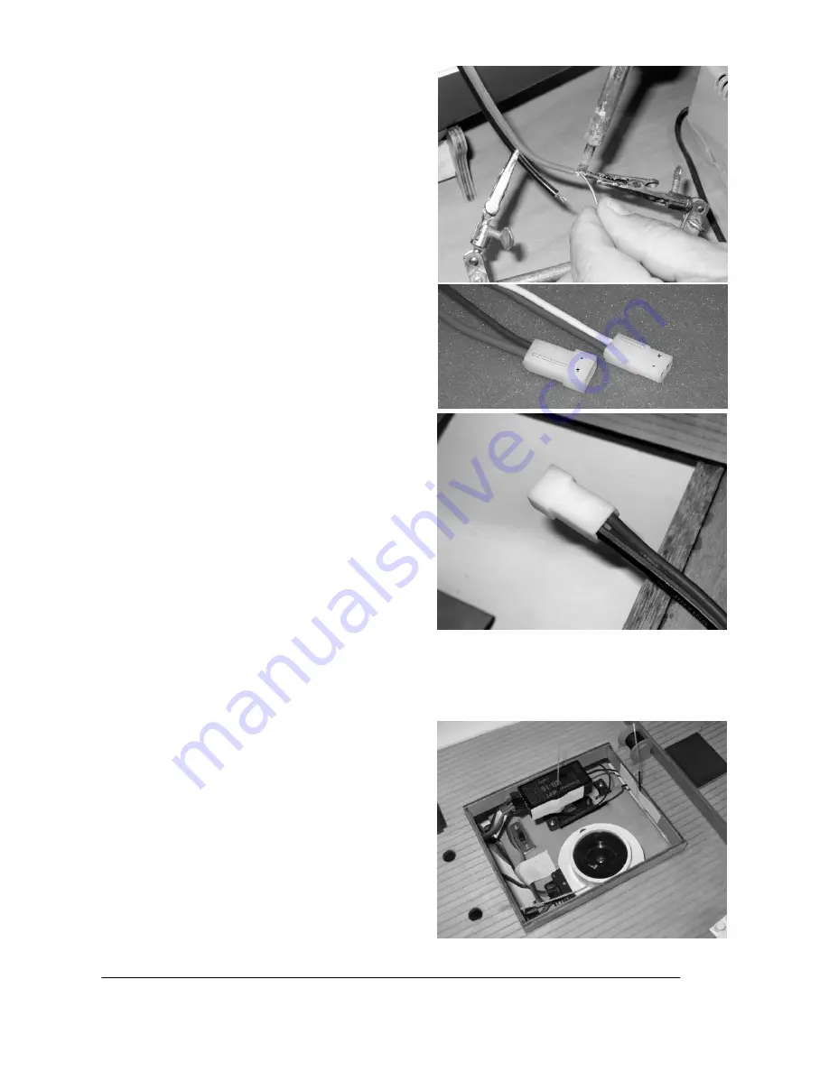
Solder a G2 connector to the motor wires, referring to
the wiring diagram on page 13 (+ is red, - is black).
Check the direction of operation of the motor: when
the battery is connected, the motor shaft must rotate
in such a way that the boat will be propelled forward.
NOTE:
the polarity of the G2 connector system is
designed in such a way that the raised lug on the
plastic housing is always the positive terminal (red
wire). If you keep consistently to this arrangement,
your drive batteries and speed controllers will always
be compatible with each other, and reversed polarity
problems will not arise. We recommend following one
of the tips below in order to make it easier to solder
the joints; this reduces the likelihood of damaging
detail features on the model with the hot soldering
iron.
TIP 1:
remove the motor: undo the grubscrews
in the propeller, then withdraw the propeller. Loosen
the motor retaining screws (accessible through the
two holes in the deck - don’t remove the screws
completely! - and then withdraw the motor to the
point where the shaft coupling is exposed. Loosen
the grubscrews in the coupling which clamp the motor
shaft, and then remove the motor from the model.
Reverse the sequence to re-install it.
TIP 2:
if you
have a friend to help you, ask him or her to hold the
boat at an angle, so that you can hold the wires
outside the hull for soldering the connector.
TIP 3:
it
is possible to solder the joints directly inside the
model (see photo) if you have access to the tool
known as a “third hand”.
Check that the screws in the shaft coupling, the
motor retaining bar and the propeller are tight, as
they may have worked loose in transit. You can
check this by pulling on the propeller: if there is axial
play in the shaft, then one of the grubscrews is loose.
Tighten any loose grubscrews cautiously, following
TIP 1
above to gain access to them.
IMPORTANT:
we recommend that you apply a drop of thread-lock
fluid, e.g. UHU schraubensicher (Order No. 952) to each grubscrew, as vibration when the boat is
operating may cause them to work loose again.
Connect the speed controller wires to those attached to the motor, and fix the controller to the inside of the
hull using Velcro (hook-and-loop) tape.
Connect the two battery connectors to the distributor lead (Order No. 3068).
Attach the receiver to the inside of the coaming under
the bridge superstructure. Stick the aerials of the
HoTT receiver in place, with the final 30 mm of the
aerial wires pointing upward; this will ensure optimum
reception. If you are using a conventional 40 MHz
receiver, the wire aerial must be deployed under the
deck, and taped in place.
IMPORTANT:
it is essential
to locate the aerial or aerials above the waterline,
otherwise radio reception will not be possible.


