GRASS VALLEY Ignite JSC-2300 SHOT Instruction Manual Download Page 33

Ignite JSC-2300 SHOT Director Robotics/Camera Controller Instruction Manual

33

Dialog Boxes


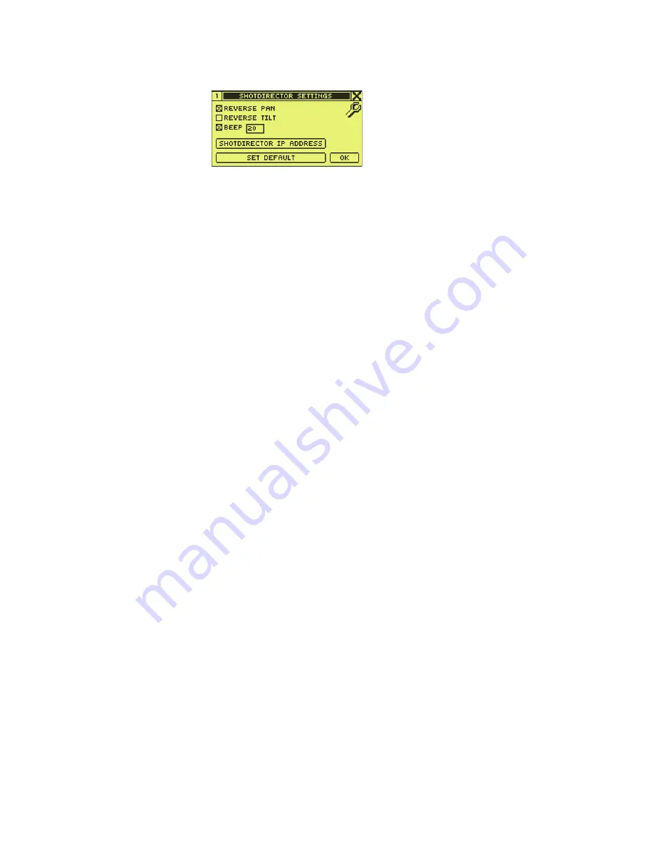
Figure 21.  SHOT Director Settings Dialog Box

PAN and TILT Orientation

The SHOT Director controller pan and/or tilt operation can be reversed, if 
necessary, to compensate for inverted camera mounting and/or operator 
location in relation to the camera. Refer to 

Figure 22

 and 

Figure 23

.

In an upright camera installation:

With the operator located behind the camera, changing pan and tilt 
operation is not necessary (normal operation is the default).

With the operator located in front of the camera, select 

REVERSE PAN

.

In an inverted camera installation:

With the operator located behind the camera, select 

REVERSE PAN


and 

REVERSE TILT

With the operator located in front of the camera, select 

REVERSE TILT

.

REVERSE PAN:

Reverse the selected camera pan direction from the joy-
stick pan direction (refer to 

PAN and TILT Orientation

 on 

page 33

)

REVERSE TILT:

Reverse the selected camera tilt direction from the joy-
stick tilt direction (refer to 

PAN and TILT Orientation

 on 

page 33

)

BEEP:

Enable/disable audible beep. When enabled, the 
numeric value adjusts the beep pitch (0-40).

SHOT DIRECTOR IP 
ADDRESS:

Access the 

SHOT DIRECTOR IP SETTINGS

 dialog box (

SHOT 

Director IP Settings Dialog Box

 on page 34

)

SET DEFAULT:

Access the 

SELECT DEFAULT SETTINGS

 dialog box (refer to 

Select Default Settings Dialog Box

 on page 35

)

OK:

Close the 

SHOTDIRECTOR SETTINGS 

dialog box

8

4

9

3_

s

c23_r0

Summary of Contents for Ignite JSC-2300 SHOT

Page 1: ...Ignite LIVE PRODUCTION CONTROL SYSTEM JSC 2300 SHOT Director Robotics Camera Controller Instruction Manual 071849300 SEPTEMBER 2006 ...

Page 2: ... Blvd Salt Lake City UT 84119 United States 7140 Baymeadows Way Suite 101 Jacksonville FL 32256 United States Including its implementation meets the requirements of the standard ISO 9001 2000 Scope The design manufacture and support of video hardware and software products and related systems This Certificate is valid until June 14 2009 This Certificate is valid as of August 30 2006 Certified for t...

Page 3: ...Ignite LIVE PRODUCTION CONTROL SYSTEM JSC 2300 SHOT Director Robotics Camera Controller Instruction Manual 071849300 SEPTEMBER 2006 ...

Page 4: ...in pdf format can be downloaded FAQ Database Solutions to problems and troubleshooting efforts can be found by searching our Frequently Asked Questions FAQ database Software Downloads Software updates drivers and patches can be down loaded Region Voice Fax Address Web Site North America 800 547 8949 Support 530 478 4148 Sales 530 478 3347 Support 530 478 3181 Grass Valley P O Box 599000 Nevada Cit...

Page 5: ...ian Certified AC Adapter 16 Certification 16 Section 1 Overview 17 Components 18 Included Components 18 Additional Components 18 Specifications 18 Section 2 Functional Description 19 SHOT Director Controller 19 SHOT Director Controller and SDC HDC Robotic Camera 19 SHOT Director Controller and Ignite Automated Production Control System 20 Controls and Indicators 21 Lens Control 21 Robotics Camera ...

Page 6: ...ontroller 39 Power On 39 Adjust LCD Dialog Box 39 Calibrate Joystick 39 Verify Controls 41 Set Audible Alarm Optional 42 Reassign Camera Quick Select Buttons Optional 42 Reset SHOT Director Defaults Optional 43 Change Pan Tilt IP Table Entries Optional 43 Setup SDC HDC Robotic Camera 44 Set Camera ID and IP Address 44 Set Pan and Tilt Orientation 46 Set Pan Tilt Soft Stops 46 Set Camera Video Char...

Page 7: ...Ignite JSC 2300 SHOT Director Robotics Camera Controller Instruction Manual 7 Contents Glossary 57 Index 63 ...

Page 8: ...8 Ignite JSC 2300 SHOT Director Robotics Camera Controller Instruction Manual Contents ...

Page 9: ...mprehensive user and service infor mation Typically it describes how to install configure troubleshoot and maintain the product and describes product operation after the product has been properly installed and configured Release Notes contain information about new features and system enhancements for a specific software version and also includes soft ware installation procedures Always check the r...

Page 10: ...10 Ignite JSC 2300 SHOT Director Robotics Camera Controller Instruction Manual Preface ...

Page 11: ...s you are qualified to do so Safety Terms and Symbols Terms in This Manual Safety related statements may appear in this manual in the following form WARNING Warning statements identify conditions or practices that may result in per sonal injury or loss of life CAUTION Caution statements identify conditions or practices that may result in damage to equipment or other property or which may cause equ...

Page 12: ...nections components or circuitry when power is present Indicates that dangerous high voltage is present within the equipment enclosure that may be of sufficient magnitude to constitute a risk of electric shock Indicates that user operator or service technician should refer to product manual s for important operating maintenance or service instructions This is a prompt to note fuse rating when repl...

Page 13: ... Do not operate this product from a power source that applies more than the voltage specified for the product Use correct voltage setting If this product lacks auto ranging power sup plies before applying power ensure that each power supply is set to match the power source Provide proper ventilation To prevent product overheating provide equip ment ventilation in accordance with installation instr...

Page 14: ...maged Properly support heavy cable bundles to avoid con nector damage Use correct power supply cords Power cords for this equipment if provided meet all North American electrical codes Operation of this equipment at voltages exceeding 130 VAC requires power supply cords which comply with NEMA configurations International power cords if provided have the approval of the country of use ...

Page 15: ...erence in which case the user will be required to correct the interference at his own expense Changes or modifications not expressly approved by Grass Valley Group can affect emission compliance and could void the user s authority to operate this equipment Canadian EMC Notice of Compliance This digital apparatus does not exceed the Class A limits for radio noise emissions from digital apparatus se...

Page 16: ... in the North America power network All other AC adapters supplied are approved for the country of use Certification Category Standard Designed tested for compliance with Safety UL1950 Safety of Information Technology Equipment including Electrical Busi ness Equipment Second edition 1993 IEC 950 Safety of Information Technology Equipment including Electrical Busi ness Equipment Second edition 1991...

Page 17: ... operate multiple robotic cameras from one clean functional joystick console Camera presets for each camera are easily programmed and recalled with the push of a few buttons Focus and iris settings are adjusted via two wheels located on the left side of the SHOT Director controller Twin sliders provide precise smooth camera control for variable pan tilt and zoom speed The joystick integrates pan t...

Page 18: ...required depends upon the specific site configuration i e the number of cameras plus the controller in the network Specifications Display LCD H 1 5 in 3 81 cm W 3 in 7 62 cm 160x80 dot matrix adjustable contrast and backlight Pan Tilt Control Self centering joystick software configured Iris Focus Control Rotary encoders Power Supply Input 100 240 V ac 50 60 Hz 15 W Output 5 V dc Dimensions Length ...

Page 19: ...ller can control up to 16 Ignite SDC HDC robotic cameras on a single TCP IP Ethernet subnetwork when con nected via network hub Figure 2 Figure 2 SHOT Director Controller and SDC HDC Robotic Camera Functional Block Diagram JSC 2300 SHOT DIRECTOR SUBNET HUB PAN TILT ROBOTIC HEAD LENS SDC HDC CAMERA BLOCK PROMPTER UP TO 15 ADDED CAMERAS 16 TOTAL SHOT DIRECTOR ROBOTIC CAMERA CONTROL SDC HDC ROBOTIC C...

Page 20: ...e SHOT Director controller through the robotic head assembly and produces SDI video out to station switching and processing equipment SHOT Director Controller and Ignite Automated Production Control System The SHOT Director controller and SDC HDC robotic cameras can operate stand alone or as an integrated part of an Ignite automated production control system Figure 3 Figure 3 Ignite SDC HDC Roboti...

Page 21: ...sfers the necessary pan tilt focus iris controls to the camera The SHOT Director controller also provides status and preset information to the Ignite system Controls and Indicators The Ignite JSC 2300 SHOT Director robotics camera controller has five basic control areas Lens Control System Control Keypad Control Buttons Robotics Control and LCD display Refer to Figure 4 Figure 4 JSC 2300 SHOT Dire...

Page 22: ...e FOCUS CONTROL is also used instead of the joystick during setup to select various setup parameters MANUAL IRIS Manual wheel type adjustment of the camera iris i e to brighten and darken the video picture A fast turn results in coarse adjustment and a slow turn results in fine adjustment AUTO IRIS must be off for the MANUAL IRIS knob to function The MANUAL IRIS control is also used instead of the...

Page 23: ... click PAN TILT SPEED CONTROL For manual speed adjustment of camera pan tilt function When the slide control is at the down limit the control is OFF ZOOM CONTROL Joystick Rotational Control For manual zoom in clockwise for tighter views and zoom out counter clockwise for wider views This control is speed proportional and speed is adjusted via the ZOOM SPEED CONTROL slider Note The joystick is also...

Page 24: ... CONTRAST and LCD BRIGHTNESS controls are located on the rear panel Refer to Figure 7 Figure 7 System Control Screen and Screen Controls Navigation Control Navigation Control Figure 8 includes the LCD display and related selec tion buttons Figure 8 System Control Navigation Button Function Home Displays the CAMERA CONTROL Home dialog box Menu Provides access to camera menus to setup change camera ...

Page 25: ...mera network Enter clear information from the LCD display Figure 10 System Control Cameras and Presets Note Up to 300 presets can be programmed for each of up to 16 controlled cam eras Back Returns the display to the previously viewed dialog box Camera Quick Select These four buttons are programmable to correspond to four camera numbers The assigned camera number appears at the bottom of the CAMER...

Page 26: ... Home Menu Setup PRESET and CAMERA buttons Splash Dialog Box The Splash dialog box Figure 12 displays for approximately three sec onds then transitions to the CAMERA CONTROL Home dialog box Figure 13 Figure 12 Splash Dialog Box Camera Control Home Dialog Box The CAMERA CONTROL Home dialog box Figure 13 is the displayed after the splash dialog box at power up It is used to view the status of the cu...

Page 27: ...l plane rotation relative to horizontal 0 degree point Zoom View the value of zoom setting Focus View the value of the focus setting Iris View the value of the iris setting or AUTO when AUTO IRIS is enabled Camera View the active camera for JSC 2300 SHOT Director controller also shown in upper left corner of LCD The controlled camera can be changed by using the Camera Quick Select buttons that cor...

Page 28: ...n On Off the camera settings menu viewed on the studio monitor BARS ON OFF Turn on off the color bars viewed on the studio mon itor AWB Turn on off camera Automatic White Balance ABB Turn on off camera Automatic Black Balance UP Navigate upward in the camera settings menu lists viewed on the studio monitor DOWN Navigate downward in the camera settings menu lists viewed on the studio monitor ITEM S...

Page 29: ...e TCP IP NETWORK dialog box refer to TCP IP Network Dialog Box on page 32 SHOTDIRECTOR SETTINGS Access the SHOTDIRECTOR SETTINGS dialog box refer to SHOT Director Settings Dialog Box on page 32 ABOUT View the JSC 2300 SHOT Director controller firmware version copyright and company information DIAG Access the DIAGNOSTICS dialog box refer to Diagnostics Dialog Box on page 36 OK Close the MAIN SETUP ...

Page 30: ... to Figure 18 Pan Tilt IP Address Dialog Box U Set the up tilt soft stop L Set the left pan soft stop R Set the right pan soft stop D Set the down tilt soft stop Pan View current Pan position L or R is displayed in parens as the camera is deflected left ot right of center Tilt View current Tilt position U or D is displayed in parens as the camera is deflected left ot right of center POINTER Change...

Page 31: ...ontroller IP address DFLT Fill IP with the default Pan Tilt IP address stored in the Lookup Table for the currently selected camera refer to Pan Tilt IP Table Dialog Box on page 31 SET Send and save IP SUBNET and CA addresses to the Pan Tilt head OK Close the PAN TILT IP ADDRESS dialog box Table View and select CAM1 through CAM16 default IP addresses When selected the camera ID and current default...

Page 32: ...splayed Select OK to close the TCP IP NETWORK dialog box Figure 20 TCP IP Network Dialog Box SHOT Director Settings Dialog Box The SHOTDIRECTOR SETTINGS dialog box Figure 21 is used to access and set SHOT Director operating characteristics To access it press the Setup button then select SHOTDIRECTOR SETTINGS It enables a user to Table 1 Pan Tilt IP Lookup Table Camera Number Default IP Address CAM...

Page 33: ...mera installation With the operator located behind the camera select REVERSE PAN and REVERSE TILT With the operator located in front of the camera select REVERSE TILT REVERSE PAN Reverse the selected camera pan direction from the joy stick pan direction refer to PAN and TILT Orientation on page 33 REVERSE TILT Reverse the selected camera tilt direction from the joy stick tilt direction refer to PA...

Page 34: ...nge the SHOT Director IP and or subnet addresses To access it press the Setup button select SHOTDIRECTOR SETTINGS then select SHOTDIRECTOR IP ADDRESS It enables a user to Figure 24 SHOT Director IP Settings Dialog Box IP Set the SHOT Director IP address SUBNET Set the subnet mask 8493_10_r0 Normal Setting Reverse Setting Upright Camera Mount 8493 10 r0 Normal Setting Reverse Setting Inverted Camer...

Page 35: ...ialog Box MAC View the MAC Media Access Control address DFLT Reset the IP address to 192 168 0 100 and the subnet mask to 255 255 255 0 defaults SAVE Save IP address and SUBNET mask changes OK Close the SHOTDIRECTOR IP SETTINGS dialog box PAN DIRECTION Set selected camera default to normal TILT DIRECTION Set selected camera default to normal SD IP ADDRESS Set default to 192 168 0 100 BEEP Set defa...

Page 36: ...d micro con troller in the joystick The raw pot values from left to right are zoom tilt pan zoom speed slider pan tilt speed slider 1st row Absolute analog to digital A D conversion values 2nd row Zero values offset from center If the first 3 values are outside the range of greater than 30 and less than 30 when the joystick is centered the joystick requires calibration refer to Calibrate Joystick ...

Page 37: ... can also be used during setup to select various setup parameters Installation and setup consists of Install SHOT Director Controller on page 38 Unpack on page 38 Connect to Network on page 38 Connect Power Supply on page 38 Power On on page 39 Setup SHOT Director Controller on page 39 Adjust LCD Dialog Box on page 39 Calibrate Joystick on page 39 Set Audible Alarm Optional on page 42 Reassign Cam...

Page 38: ...he factory to enable the SHOT Director controller and one camera to establish communication immediately on the network In order to connect a second camera you must change the IP address of the first camera before connecting the next then repeat this process until all cameras are uniquely addressed 1 For Multiple camera operation connect an Ethernet cable between the 10 100 MBIT ETHERNET connector ...

Page 39: ...is initial calibration every time the SHOT Director controller powers on the CAMERA CONTROL home dialog box Figure 13 appears The Grass Valley splash dialog box Figure 12 appears briefly and then the Center Joystick Then Press Enter dialog box Figure 27 appears Adjust LCD Dialog Box If necessary adjust the LCD CONTRAST and LCD BACKLIGHT on the rear panel Figure 11 of the SHOT Director controller t...

Page 40: ... dialog box appears Do not touch the Joystick The Zeroing Joystick Please Wait dialog box displays approxi mately 5 seconds Figure 28 Zeroing Joystick Dialog Box 2 When the zero calibration process finishes the Levels dialog box Figure 29 appears Figure 29 Levels Dialog Box 3 Move the joystick control and the sliders to their extreme positions so the SHOT Director controller can record minimum and...

Page 41: ...HOT Director controls is verified 1 Press the Setup button Figure 8 The MAIN SETUP MENU dialog box Figure 15 appears 2 Select DIAG Figure 15 The DIAGNOSTICS dialog box Figure 26 appears and the AUTO IRIS indicator blinks continuously 3 Center the joystick then verify that the first three sets of numbers in the second row of RAW POT VALUES are greater than 30 and less than 30 If the values are outs...

Page 42: ...the pitch set to 20 mid range 1 Press the Setup button Figure 8 The MAIN SETUP MENU dialog box Figure 15 appears 2 Select SHOTDIRECTOR SETTINGS Figure 15 The SHOT DIRECTOR SETTINGS dialog box Figure 21 appears 3 To turn off the audible alarm use the joystick to uncheck the BEEP checkbox Figure 21 4 To change the BEEP pitch use the joystick to select the pitch box Figure 21 type in a number from 0 ...

Page 43: ...ure 21 appears 3 Select SET DEFAULT Figure 21 The SELECT DEFAULT SETTINGS dialog box Figure 25 appears 4 With the joystick select check or uncheck any of the selection boxes for PAN DIRECTION TILT DIRECTION SD IP ADDRESS BEEP HOT KEYS or DEL PRESET Change Pan Tilt IP Table Entries Optional CAUTION Do not change the default CAM 16 IP address This is the default factory address assigned to all new S...

Page 44: ...p 4 and Step 5 for each camera ID IP address that needs modified 6 Select SAVE to save the changes to the table Note If necessary reset the Pan Tilt IP Address table to factory defaults listed in Table 2 by selecting DFLT from the PAN TILT IP TABLE dialog box then selecting SAVE Setup SDC HDC Robotic Camera Set Camera ID and IP Address Note Each SDC HDC camera pan tilt head is factory pre configur...

Page 45: ...PAN TILT IP ADDRESS dialog box Figure 18 appears 4 Select any of the IP field boxes and change them to the desired camera ID and IP address shown in Table 2 Note Ensure SUBNET is set to 255 255 255 0 and CA matches the SHOT Director default IP address 192 168 0 100 5 Select SET to send the new IP SUBNET and CA addresses to the Pan Tilt head 6 From the CONFIRM dialog box Figure 32 select YES to sav...

Page 46: ... camera modified in the top right corner 12 Repeat process for each camera one at a time Set Pan and Tilt Orientation Note The SHOT Director controller pan and or tilt operation can be reversed if nec essary to compensate for inverted camera mounting and or operator loca tion in relation to the camera Refer to PAN and TILT Orientation on page 33 1 Press the Setup button Figure 8 The MAIN SETUP MEN...

Page 47: ...ll display as a checked box If no User soft stops exist all boxes will be unchecked 4 Select POINTER to change the joystick to a pointing device 5 Uncheck the U up D down L left and or R right check box s for the softstops being changed 6 Select JOY to change the joystick to motion device 7 Using the joystick pan or tilt the camera to the desired soft stop position In the example below Figure 33 t...

Page 48: ...object that fills at least 50 of the studio monitor screen necessary for Automatic White Balance adjustment 2 Press the Menu button Figure 8 The HD SD CAMERA dialog box Figure 14 appears To set the Automatic White Balance select AWB To set Automatic Black Balance select ABB To display the Camera Setting Menu on the studio monitor select MENU ON OFF then select UP or DOWN to navigate to the desired...

Page 49: ...onsists of Power On Off on page 49 Camera Selection on page 50 Camera Presets Assignment on page 50 Recall Camera Presets on page 51 Manual Camera Control on page 51 Power On Off Power On Note For more information on powering up other devices on the network see the operation manual that came with the device 1 Ensure that one camera is connected and powered on Refer to Connect to Network on page 38...

Page 50: ...re 34 appears Figure 34 CAMERA Select Dialog Box 2 Using the joystick and keypad in the CAMERA box type the camera number and then click OK The CAMERA dialog box shows the selected camera number in the upper right Method 2 1 Press CAMERA The CAMERA Select dialog box Figure 34 appears 2 Select the CAMERA box 3 Using the FOCUS CONTROL wheel or AUTO IRIS wheel rotate the wheel to select the camera nu...

Page 51: ...on 5 Click STORE Note Each SHOT Director controller can store up to 300 preset positions for each camera 6 Repeat Step 1 through Step 5 for each camera preset Recall Camera Presets 1 Select a camera refer to Camera Selection on page 50 2 On the Camera and Preset keypad press PRESET The ENTER PRESET dialog box Figure 35 appears 3 In the PRESET box type the preset number to recall Note In the follow...

Page 52: ...d Note This is a variable speed control When the PAN TILT SPEED CONTROL is at the down limit the control is off Moving the control up gradually increases the PAN TILT speed Move the slider Up to increase pan tilt speed Down to decrease pan tilt speed Direction Note Joystick control of pan tilt depends on camera mounting and camera oper ator position Refer to PAN and TILT Orientation on page 33 Pan...

Page 53: ...Note This is a variable speed control When the ZOOM SPEED CONTROL is at the down limit the control is off Moving the control up gradually increases the zoom speed Move the slider Up to increase zoom speed Down to decrease zoom speed View Rotate the joystick knob Clockwise for a tight view Counterclockwise for a wide view ...

Page 54: ...54 Ignite JSC 2300 SHOT Director Robotics Camera Controller Instruction Manual Section 4 Operation ...

Page 55: ... after troubleshooting please contact your authorized Grass Valley reseller or contact Grass Valley Customer Support directly See Contacting Grass Valley on page 4 Table 3 Troubleshooting Problem Cause Solution Matrix Problem Cause Solution Power Mains power OFF Energize Mains power Power supply not connected to Mains Connect power supply to Mains Power supply not properly connected to SHOT Direct...

Page 56: ... are not set to zero full down position In multiple camera systems select another camera and verify that it can be controlled If selected camera can not be controlled troubleshoot SHOT Director and hub If selected camera can be controlled troubleshoot failed camera Refer to camera manual Network hub Ensure all devices are powered Use crossover cable between SHOT Director controller and pan tilt he...

Page 57: ... color Chroma Gain chroma color saturation The gain of an amplifier as it pertains to the intensity of colors in the active picture Clip A threshold level adjustment to which the keying attribute luminance chrominance is compared for generating the internal key control signal Clip in conjunction with gain sets the switching point between the back ground and the key fill Also see Gain Component Vid...

Page 58: ... blue Chroma hue and luminance make up the three character istics of television color I Interlace A system of video scanning where the odd and even numbered lines of a picture are pre sented consecutively as two separate inter leaved fields The two fields required to make a complete picture are called a frame IP Internet Protocol A data oriented protocol used for communi cating data across a packe...

Page 59: ...sub sig nal phase is different on each successive scan line to reduce picture artifacts Pixel A picture element A pixel is a digital sample of the luminance and color values of a pic ture at a single point ProAv Professional Audio Video production Q R S Saturation The degree of purity of a color Adding white to a color reduces its degree of saturation SD Standard Definition Serial Digital Interfac...

Page 60: ...he switcher s output s Also does transitions between sources and special effects video mixing wiping keying and such Sync 1 General term for a synchronizing signal or signal component Digital systems gener ally employ an analog external timing refer ence signal such as color black or tri level sync to synchronize different pieces of equipment Within the digital signal itself however synchronizing ...

Page 61: ...e a type of prompter A TTL prompter mounts horizontally in front of the camera A glass screen mounted 45 above the prompter reflects the script so that the announcer can read the text while look ing at the camera behind the screen U V Video Switcher See Switcher W X Y Z ...

Page 62: ...62 Ignite Glossary Glossary ...

Page 63: ... 21 rear panel 26 robotics camera 22 system 24 D Default reset 43 Diagnostics dialog box 36 Dialog Boxes 26 Camera Control Home 26 Diagnostics 36 HD SD Camera 27 Main Setup Menu 28 Pan Tilt IP Address 30 Pan Tilt IP Table 31 Pan Tilt Settings 29 Pan Tilt Soft Stops 29 Select Default Settings 35 SHOT Director IP Settings 34 SHOT Director Settings 32 Splash 26 TCP IP Network 32 documentation online ...

Page 64: ...l Camera Presets 51 Other Documentation 9 Overview 17 P Pan Tilt control 23 52 direction 52 IP Address dialog box 30 IP Lookup Table 32 IP Table dialog box 31 orientation 33 46 Settings dialog box 29 Soft Stops dialog box 29 Soft Stops setup 46 speed 23 52 Power Off 50 On 39 49 Power button 22 Power Supply connection 38 Preface 9 Presets control 25 Q Quick Select button reassignment 42 R Rear pane...

Page 65: ...T Director IP Settings dialog box 34 Settings dialog box 32 software download from web 4 Specifications 18 Splash dialog box 26 Standard Documentation 9 System control 24 camera specific 25 cameras and presets 25 LCD 24 navigation 24 T TCP IP Network dialog box 32 Troubleshooting 55 Camera control 56 Power 55 Problem Cause Solution Matrix tbl 55 U Unpack 38 V Verify controls 41 W web site document...

Page 66: ...66 Ignite JSC 2300 SHOT Director Robotics Camera Controller Instruction Manual Index ...

Reviews: