background image

2-20

Checks and Preparation

2.14 Precautions to Observe When Performing Measurement

Please be sure to read the following carefully in order to prevent electric shocks or shorts.

DANGER

• Do not apply voltage of AC30 Vrms or 60 VDC or above between the analog input section and main unit (GND

terminal), or between each analog input channel.

• Do not apply radio-frequency signals with high voltage (50 KHz or above).

• Be sure to use only the AC adapter provided as a standard accessory. The rated power supply range for the

adapter is 100 to 240 VAC, and the rated frequency is 50/60 Hz. Do not use any other voltages.

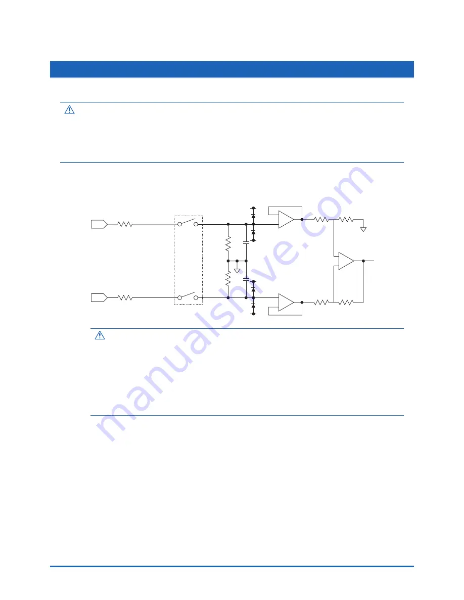
Input Circuit Diagram for Analog Input (Voltage, Thermocouples)

50

50

500k

500k

0.05

µ

F

0.05

µ

F

Channel Switching Relay

+

CAUTION

Capacitors have been incorporated into the input circuit to increase the noise elimination capability.
After voltage measurement, when the inputs have been disconnected, there will still be some electric
charge remaining. Before starting another measurement operation, short-circuit the + and - terminals to
enable self-discharge.
The GL800 has a scan system.
While in the status (open) in which signals are not input to the input terminal, measured results may be
influenced by signals from other channels.
In such a case, turn OFF the input setting or short c/-.
If signals are input correctly, measured results are not influenced by other channels.

Summary of Contents for midi LOGGER GL800

Page 1: ...GL800 USER S MANUAL MANUAL NO GL800 UM 152...

Page 2: ...is a lot of noise or where the power supply is unstable we recommend that you ground the GL800 2 When a high voltage signal cable has been connected to the main unit s analog signal input terminal avo...

Page 3: ...stated specifications if the GL800 is used in an environment which is subject to strong electromagnetic interference 7 Insofar as possible position the GL800 input signal cables away from any other ca...

Page 4: ...or WARNING This category provides information that if ignored is likely to cause fatal or serious injury to the operator CAUTION This category provides information that if ignored could cause physical...

Page 5: ...may result in a fire hazard or electrical shock After checking that smoke is no longer being generated contact your sales representative or nearest Graphtec vendor to request repair Never try to perfo...

Page 6: ...ng to the power supply connector Adhesion of foreign matter may cause a fire hazard due to electrical shock or current leakage Never use a damaged power cord Use of a damaged cord may result in a fire...

Page 7: ...asp the power cord s plug or the signal input cable s connector Pulling the cord cable itself damages the cord cable resulting in a fire hazard or electrical shock If fluid or foreign matters enters i...

Page 8: ...h action may cause the GL800 to break down Never clean the GL800 using a volatile solvent such as thinner or benzine Such action may impair the GL800 s performance Clean off any soiled areas using a s...

Page 9: ...ing 2 2 2 2 Checking the Accessories 2 2 2 3 GL800 Part Names and Functions 2 3 2 4 Connecting the Power Cable and Turning on the Power 2 4 Connecting to an AC Power Supply 2 4 Connecting to a DC Powe...

Page 10: ...AN TRACE POSION 3 5 3 TIME DIV 3 5 4 MENU 3 6 5 QUIT LOCAL 3 6 6 Direction keys 3 6 7 ENTER 3 7 8 FAST FORWARD key KEY LOCK 3 7 9 START STOP USB Drive Mode 3 7 10 REVIEW 3 8 11 DISPLAY 3 9 12 CURSOR A...

Page 11: ...x Contents 4 3 Accessory Option Specifications 4 7 Control Software 4 7 Accessories 4 7 Battery Pack B 517 Option 4 7 Humidity Sensor B 530 Option 4 8 Options 4 8 4 4 External Dimensions 4 9 Index I 1...

Page 12: ...al description of the GL800 and its features CHAPTER 1 General Description 1 1 Overview 1 2 Features 1 3 Operating Environment 1 4 Notes on Temperature Measurement 1 5 Notes on Using the Monitor 1 6 C...

Page 13: ...the GL800 s 5 7 inch TFT color liquid crystal display you can confirm the waveforms of measured data and each channel s settings at a glance 2 Easy operation is achieved through a straightforward menu...

Page 14: ...over voltage category The GL800 conforms to the IEC664 installation category 1 CHECKPOINT If condensation occurs Condensation occurs in the form of water droplets on the device surfaces and interior w...

Page 15: ...eed refer to page 3 20 1 5 Notes on Using the Monitor The monitor is an LCD display unit and so the display will vary depending on the operating environment CHECKPOINT If the screen saver function is...

Page 16: ...on the Power 2 5 Connecting the Signal Input Cables 2 6 Logic Alarm Cable Connection and Functions 2 7 Attaching USB Memory 2 8 Connecting to a PC 2 9 Using the Battery Pack Option 2 10 Connecting the...

Page 17: ...0 60 Hz 1 Item Option No Remarks Battery pack B 517 7 2V 2200mAh DC drive cable B 514 2 m Bare tips Humidity sensor B 530 3 m length with dedicated power connector Extension terminal base set B 537 Ex...

Page 18: ...N when the power is ON START ON during data capture CHARGE ON while the battery is charging Control panel keys AC adapter jack External input output terminal LOGIC PULSE LOGIC PULSE input EXT TRIG Tri...

Page 19: ...AC cable into the AC adapter 2 Connect the output side of the AC adapter to the connector on the GL800 3 Using the flat blade screwdriver press against the minus button above the GND terminal while c...

Page 20: ...able B 514 2m to enable it to be connected to the DC power supply 2 Connect the DC output side to the power supply connector on the GL800 DC drive cable B 514 White side Shielded lead side 3 Connect t...

Page 21: ...isolated within each channel Terminal b is shorted within all channels CH1 CH20 b Direct voltage Compensation copper wire Item Description Input configuration Isolated input scanning Analog voltage 20...

Page 22: ...larm Output Item Description Number of output channels 4 Output format Open collector output 5 V 10 K pull up resistance Contact capacity 5 V to 24 V 100 mA or below Item Description Number of input c...

Page 23: ...dotted line 2 White with black dotted line 3 Yellow with red dotted line 4 Yellow with black dotted line Trigger input Pink with red dotted line GND Pink with black dotted line Shielded Orange with re...

Page 24: ...nserting a USB Memory Attach the USB memory to the USB memory terminal CAUTION When you attach the USB memory to GL800 be careful during handling so as not to bump or drop the unit Specifications of s...

Page 25: ...the USB cable to connect the GL800 to a PC CHECKPOINT If the USB cable is used the USB driver must be installed in your PC Please refer to Application Software Instruction Manual for the installation...

Page 26: ...n Use a LAN cable to connect the GL800 to a PC Cable Types Use a crossing cable when connecting directly to a PC without using a hub Use a straight cable when using a hub LAN cable LAN cable crossing...

Page 27: ...her one or two battery packs can be attached To connect one pack connect to either one of the connectors Attaching two battery packs allows longer operational time CAUTION When attaching two battery p...

Page 28: ...CHARGE LED lights CHECKPOINT GL800 is equipped with a temperature monitor function which starts automatic charging as soon as it is cooled down Therefore depending on the internal temperature chargin...

Page 29: ...or the B 530 option to the desired terminals and then insert the round connector into the 5V OUT connector on the GL800 CAUTION Do not use the sensor in a strong electrolyte envronment Measured result...

Page 30: ...sure the GL800 s power is OFF when removing or mounting terminal units To Remove Pull the terminal unit out towards the direction indicated by the arrow while pressing the two locks at the bottom of...

Page 31: ...e terminal unit into the slots of the GL800 and push in the unit until the lock tabs at the bottom of the unit are securely locked 1 Insert tabs at the top of the terminal unit into the slots 2 Press...

Page 32: ...erminal unit into the slots of the extension terminal base unit and push in the unit until the lock tabs at the bottom of the unit are securely locked 3 Connect the extension terminal cable to the ext...

Page 33: ...L800 s power is OFF when mounting the extension terminals B 538 Set Contents Extension Terminal Base Unit 1 20 Channel Terminals 1 Connection Plate 1 M4 x 6 Flat Head Screw 4 To Mount 1 Connect the ex...

Page 34: ...nd of the extension terminal cable to GL800 Press in the cable until it is securely locked CAUTION When connecting additional terminals make sure they are added in a continuous manner Any terminals om...

Page 35: ...e any other voltages Input Circuit Diagram for Analog Input Voltage Thermocouples 50 50 500k 500k 0 05 F 0 05 F Channel Switching Relay CAUTION Capacitors have been incorporated into the input circuit...

Page 36: ...ead to connect the chassis GND of the measurement object to the GL800 chassis GND It will become even more effective if the ground potentials are the same The effects of the digital filter function wi...

Page 37: ...discharged and the date and time may revert to the initial settings If this happens recharge the battery before using the GL800 How to Recharge the Rechargeable Battery Using the AC adapter provided...

Page 38: ...r describes the setting and measurement procedures for the GL800 CHAPTER 3 Settings and Measurement 3 1 Window names and functions 3 2 Key Operation 3 3 Operation Modes 3 4 Setting Menus 3 5 WEB Serve...

Page 39: ...of each channel Use the key to select the channel you want to activate enlarged display The waveform of the active channel is displayed at the top 10 Quick settings Displays items available for easy...

Page 40: ...t scale of the currently active channel 15 Waveform display Displays the waveform of the input signal 16 Upper limit scale Displays the upper limit scale of the currently active channel 17 Data captur...

Page 41: ...nels with a larger number Pressing this key can switch among the following items Switch channels of the digital display area Switch channels of the AMP settings Switch channels of the trigger alarm le...

Page 42: ...witch the channels and keys to change the setting values When ALL is set setting values for CH1 is reflected on other channels When CH1 is OFF ALL cannot be set 3 TIME DIV Press the left right key of...

Page 43: ...o cancel remote status in which keys are disabled through interface control To close the menu screen To quit data replay To return the Enlarged Waveform Screen Digital Calculation Display Screen to th...

Page 44: ...operation mode in the file box To set key lock Hold down the left right FAST FORWARD key for at least two seconds press again to unlock A password for canceling the key lock can be specified See page...

Page 45: ...the USB device to the GL800 3 While pressing the GL800 START STOP key turn the power ON 4 The external storage media is recognized by the PC and data exchange becomes possible 10 REVIEW This key is us...

Page 46: ...ing when stopped and Capturing Pressing this key switches the window display as follows Waveform Digital Screen Default Expanded Waveform screen Displays the waveform in full screen mode Digital Calcu...

Page 47: ...ined alarm is cleared 13 FILE This key is use for operations related to the Internal memory and USB device copy and delete Copies the window Saves data between cursor A and cursor B during replay can...

Page 48: ...ng are basic operation procedures for settings 1 Press the MENU key to open each menu 2 Use the key to move the cursor to the items you want to set 3 Press the ENTER key to display a list of setting v...

Page 49: ...cording or USB device USB Drv Recording Dual View Replaying The current waveform display and data on capturing Memory Recording is being replayed USB Drv Recording Replaying Captured data is being rep...

Page 50: ...erations available during dual view replaying CAUTION Captured data can only be displayed for the double window buffer portion Dual view buffer capacity is 512 KB Time of Capturing Capture file name C...

Page 51: ...ey is used to change settings Menu operations during data The MENU key is used to move the cursor search data and replay set calculation Moving cursors The CURSOR key is used to switch between cursors...

Page 52: ...00 Range Voltage 20 50 100 200 500 mV 1 2 5 10 20 50 1 5 V Temperature TC K TC J TC T TC R TC E TC B TC S TC N TC W PT100 JPT100 PT1000 Filter Off 2 5 10 20 40 Function Off On effective when On has be...

Page 53: ...midity Used for measuring humidity Range Specifies the range of signal input to be measured Voltage 20 50 100 200 500mV 1 2 5 10 20 50 1 5V Temperature TC K TC J TC T TC R TC E TC B TC S TC N TC W PT1...

Page 54: ...culated using a ratio of the Meas Value or EU Output Value settings is displayed when the converted value cannot be processed by GL800 a Meas Value Specifies the numeric value to be converted Set two...

Page 55: ...unit The Unit displayed here is the type of unit selected by the Select setting To specify a unit that is not displayed here specify a user defined character string as the Unit setting Moreover the se...

Page 56: ...ative number of pulses for each sampling interval from the start of measurement Inst Displays the number of pulses for each sampling interval Pulse Slope Sets the slope direction to count the number o...

Page 57: ...number of channels in which input settings are NOT set to OFF CAUTION To use the digital filter function you must set the AC power supply frequency accurately Follow the instructions on page 3 28 to e...

Page 58: ...lculation is not performed Average Displays the simple average value during data capture Max Displays the maximum value during data capture Min Displays the minimum value during data capture Peak Disp...

Page 59: ...d time arrives when repeated capturing is set to Off Stops capturing data when a specified time arrives when repeated capturing is set to On This setting is used when you want to stop capturing data a...

Page 60: ...to or falls below the specified level Win In Used to specify the upper and lower limits for each channel When the signal level goes within or is within either limit a trigger alarm is generated Win Ou...

Page 61: ...r each channel OR Starts stops capturing data when at least one trigger condition is met AND Starts stops capturing data only when all trigger conditions are met Pulse Specifies the trigger alarm for...

Page 62: ...goes from High to Low L Enabled when the logic signal goes from Low to High USER settings This menu is used to store setting conditions for each user By switching between users these setting conditio...

Page 63: ...ibed in this file Macro operation flow Macro description example file name xxx GMA CAUTION Refer to the Interface Command Table for details on commands supported by GL800 on a separate sheet The Inter...

Page 64: ...efault value 192 168 0 1 Subnet mask Sets the subnet mask Default value 255 255 255 0 Port number Sets the port number Specify a value from 1024 to 65535 Default value 8023 Gateway Sets the gateway ad...

Page 65: ...mpensation This parameter enables room temperature compensation settings when thermocouples are used You can select either internal or external room temperature compensation Internal The GL800 s room...

Page 66: ...l filter function Number of Measuring Channels is the number of channels in which input settings are NOT set to OFF Date Time This parameter sets the date and time Language This parameter sets the GL8...

Page 67: ...ture start time as the file name User Sets to a user defined name Execute Executes bitmap save Save Data Between Cursors When captured data is replayed the data between cursors A and B is saved Folder...

Page 68: ...ption Change the operation of the file box Show properties Display details of a file or folder Select file folder Select files or folders to write data Create new folder Create a new folder Create new...

Page 69: ...lder named TEST is created for captured data and automatically saved In the Data save Destination choose Select folder and press the ENTER key Use the key to move to the target folder Use the key to s...

Page 70: ...ose Select file folder Use the key to move the cursor to the created TEST folder and press the ENTER key Select OK to close the screen Text input Related to text input operations such as annotation EU...

Page 71: ...e Next Search Prev Search Statistical Calculation Statistical Calculation Off Average Max Min Peak RMS between cursors Execute Operation mode Description Operation method Text input A Upper case alpha...

Page 72: ...the specified date time Cursor Sync Moves cursors A and B simultaneously Cursor A is always the fulcrum Date Search This function searches within the captured data using the specified method CH Selec...

Page 73: ...may be switched to display another group of 10 channels NAVI menu The NAVI menu can be displayed in three modes Free Running Recording and Replay Quick settings You can easily set two items on the di...

Page 74: ...sword is set at factory default Operation flow 1 Set the password Press the and ENTER keys at the same time to display the password setting screen shown below Specify a 4 digit password Use the keys t...

Page 75: ...n Enlarging GL800 display screen Linking to FTP Linking to our Web site Setting the URL The URL Uniform Resource Locator must be correctly set according to your network environment Follow the procedur...

Page 76: ...the LCD screen of GL800 Digital Displays the GL800 measured value digitally Download of device file Allows data captured with GL800 to be downloaded to your PC via FTP Graphtec Web site Accesses to ou...

Page 77: ...tal display area Press this key to switch among MONITOR SPAN POSITION and TRACE Cursor keys Screen update speed Specifies the speed in which the screen is updated Available update speeds are 2 5 and 1...

Page 78: ...ead pnly files Upload file Delete file folder Create file folder Change file name folder name To enable data to be written to the GL800 the login account name must be changed please use the following...

Page 79: ...his chapter describes the basic specifications for the GL800 CHAPTER 4 Specifications 4 1 Standard Specifications 4 2 Function Specifications 4 3 Accessory Option Specifications 4 4 External Dimension...

Page 80: ...input 8 5 to 24 VDC Battery pack option 7 2 VDC 2200 mAh 2 packs mountable Power consumption AC power consumption when the supplied AC adapter is used DC power consumption Normal status is when LCD b...

Page 81: ...files from internal memory and USB memory USB functions USB drive mode Transfers and deletes files from internal memory Realtime data transfer speed 1 100 msec 10 ch maximum Item Description Display...

Page 82: ...p input voltage Between input terminal input terminal 60 Vp p Between input terminal GND 60 Vp p Withstand voltage Between input terminal input terminal 1 minute at 350 Vp p Between input terminal GND...

Page 83: ...minimum value RMS Number of operations maximum of 2 can be set simultaneously Method Realtime and between cursors specified during data replay Note Calculation results are displayed in Digital screen...

Page 84: ...dgment window judgment logic pattern judgment pulse judgment Pulse input Revolutions mode engines etc Function Counts the number of pulses per second enables them to be converted to rpms Spans 50 500...

Page 85: ...V 2200 mAh Battery type Lithium secondary battery Running time Up to two packs can be mounted When LCD is ON Battery pack x 1 brightness MAX approx 2 5 hours Battery pack x 1 brightness MIN approx 3...

Page 86: ...m Name Model Description Battery pack B 517 7 2V 2200mAh DC drive cable B 514 2m bare tips Humidity sensor B 530 3m with dedicated power connector Extension terminal base set B 537 Extension terminal...

Page 87: ...Specifications 4 9 4 4 External Dimensions Dimensional precision 5 mm Unit mm...

Page 88: ...PC 2 10 Power Cable 2 4 Control Software 5 7 CURSOR key 3 10 D Data capture bar 3 3 Data replay menu 3 34 3 36 DATA settings 3 20 Date and Time 2 22 Date Time 3 28 3 29 DC Drive cable 2 2 Power Suppl...

Page 89: ...y 2 22 Remote lamp 3 2 Repeated capturing 3 22 Replaying 3 14 Return to default settings 3 28 3 29 REVIEW key 3 8 Room Temp Compensation 3 28 S Sampling Interval 3 20 Screen Saver 3 28 Send burnout Al...

Page 90: ...Index I 3 Waveform control display area 3 2 Waveform display area 3 3...

Page 91: ...I 4 Index...

Page 92: ...The specifications etc in this manual are subject to change without notice GL800 UM 152 Apr 1 2007 2nd edition 01 GRAPHTEC CORPORATION...

Page 93: ...503 10 Shinano cho Totsuka ku Yokohama 244 8503 Japan Tel 81 045 825 6250 Fax 81 045 825 6396 Email info graphteccorp com Web www graphteccorp com Printed in Japan...

Reviews: