


FCX2000-UM-251-9370 2-22
2 Setup procedure
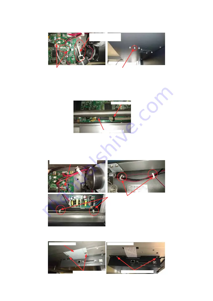
(11)
Disconnect the X motor cables from the main board (J11.J17).
And then remove the cable core tie from the control box.
Disconnect the X motor cables from these
connectors (J11, J17).
Remove the cable core
tie from the control box.
Pinch the bottom of cable core tie by using
the needle-nose pliers from bottom of control
box, and then remove the cable core tie from
the control box.
(12) Disconnect the control panel cable from the main board.
And then remove the control panel cable tie from the main board.
Control panel cable tie
Control panel cable
(13)
Disconnect the Emergency Stop Switch cable from the main board (J10).
And then remove all cable ties of the Emergency Stop Switch cable from the control box.
Disconnect the
Emergency Stop
Switch cable from the main
board (J10)
.
Remove the cable ties from the control box.
(14)
Remove the two M4L8 binding head screws holding the X flexible cable cover, and then detach it.
And then Remove the two M4L8 binding head screws holding the IF side of control box.
X flexible cable cover
M4L8 binding head screw
IF side of control box
M4L8 binding head screw
Summary of Contents for FCX2000 SERIES
Page 1: ...CUTTING MACHINE SERVICE MANUAL FCX2000 FCX2000 UM 251 10 9370...
Page 2: ......
Page 9: ...FCX2000 UM 251 9370 vii 13 Target electrical component for WEEE instruction 13 1...
Page 71: ...FCX2000 UM 251 9730 5 2 5 Daily Maintenance...
Page 73: ......
Page 75: ......
Page 212: ...FCX2000 UM 251 9370 11 2 11 PARTS LIST Main Outer 2 1 5 5 7 8 9 10 11 12 13 6 3 3 4 4...
Page 230: ...FCX2000 UM 251 9370 12 3 12 BLOCK DIAGRAMS AND CIRCUIT DIAGRAMS 2 13 CONNECT_1...
Page 231: ...FCX2000 UM 251 9370 12 4 12 BLOCK DIAGRAMS AND CIRCUIT DIAGRAMS 3 13 CONNECT_2...
Page 232: ...FCX2000 UM 251 9370 12 5 12 BLOCK DIAGRAMS AND CIRCUIT DIAGRAMS 4 13 CONNECT_3...
Page 233: ...FCX2000 UM 251 9370 12 6 12 BLOCK DIAGRAMS AND CIRCUIT DIAGRAMS 5 13 FPGA...
Page 234: ...FCX2000 UM 251 9370 12 7 12 BLOCK DIAGRAMS AND CIRCUIT DIAGRAMS 6 13 IF...
Page 235: ...FCX2000 UM 251 9370 12 8 12 BLOCK DIAGRAMS AND CIRCUIT DIAGRAMS 7 13 MEMORY...
Page 236: ...FCX2000 UM 251 9370 12 9 12 BLOCK DIAGRAMS AND CIRCUIT DIAGRAMS 8 13 DRIVER...
Page 237: ...FCX2000 UM 251 9370 12 10 12 BLOCK DIAGRAMS AND CIRCUIT DIAGRAMS 9 13 Pen Encoder Pen Encoder...
Page 238: ...FCX2000 UM 251 9370 12 11 12 BLOCK DIAGRAMS AND CIRCUIT DIAGRAMS 10 13 LAN...
Page 239: ...FCX2000 UM 251 9370 12 12 12 BLOCK DIAGRAMS AND CIRCUIT DIAGRAMS 11 13 LPC4357_1...
Page 240: ...FCX2000 UM 251 9370 12 13 12 BLOCK DIAGRAMS AND CIRCUIT DIAGRAMS 12 13 LPC4357_2...
Page 241: ...FCX2000 UM 251 9370 12 14 12 BLOCK DIAGRAMS AND CIRCUIT DIAGRAMS 13 13 LPC4357_3...
Page 243: ...FCX2000 UM 251 9370 12 16 12 BLOCK DIAGRAMS AND CIRCUIT DIAGRAMS 12 4 Y Relay Board PN4031 03...


