


CE5000-UM-251-9370
6-32
6. DISASSEMBLY AND REASSEMBLY
6.2.15 How to Replace the Main Board
How to detach the main board
(1) Detach the right cover (see Subsection 6.1.1).
(2) Detach the front guide (see Subsection 6.1.5 or 6.1.6).
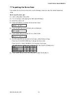
RS-232C interface
USB interface
M3L6 binding head screw
(3) Remove the two screws holding the RS-232C interface connector to the chassis.
(4) Remove the screw holding the USB interface connector to the chassis.
(5) Disconnect all the cables and flexible cables from their connectors on the main board.
(6) Remove the four M3L6 binding head screws holding the main board.
(7) Detach the main board from the chassis.
How to reinstall the main board
(1) Reattach in the reverse order in which it was detached.
(2) Install the main board corresponding to each model when replaying to the new main board.
(3) If you have “BOOT START ERROR” when you replaced the main board, Install the firmware for new
main board (see Section 7.10).
(4) Perform any adjustments required (see Section 7.2).
Summary of Contents for CE5000-120
Page 1: ...CE5000 UM 251 09 9370 CE5000 Series SERVICE MANUAL MANUAL NO CE5000 UM 251 CUTTING PLOTTER...
Page 24: ......
Page 28: ...CE5000 UM 251 9370 3 4 3 OPERATIONS CE5000 120AP ENTER key ENTER key...
Page 34: ......
Page 36: ......
Page 72: ......
Page 90: ......
Page 96: ......
Page 100: ......
Page 116: ......


