


CE5000-UM-251-9370
2-13
2. PARTS NAMES and FUNCTIONS
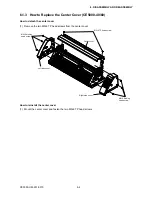
(3) Mount the CE5000 cutting plotter on the stand by inserting the positioning pins on the stand into the
positioning holes on the underside of the cutting plotter. Fasten using the four coin screws or hexagonal
socket bolts (M6).
CE5000-60
CE5000-120
Stand
Hexagonal
socket bolts (M6)
CE5000-120
Positioning pins
Coin screws
Stand
CE5000-60
Positioning pins
(4) Pull out the sheet support pipe and attach the sheet. Divide the sheet over the center bar, and then
fasten the sheet to the sheet support pipe using the press-studs.
CE5000-60
CE5000-120
Sheet
Press-studs
Sheet support pipe
Sheet
Divide over the center bar
Press-studs
Sheet support pipe
Divide over
the center bar
Summary of Contents for CE5000-120
Page 1: ...CE5000 UM 251 09 9370 CE5000 Series SERVICE MANUAL MANUAL NO CE5000 UM 251 CUTTING PLOTTER...
Page 24: ......
Page 28: ...CE5000 UM 251 9370 3 4 3 OPERATIONS CE5000 120AP ENTER key ENTER key...
Page 34: ......
Page 36: ......
Page 72: ......
Page 90: ......
Page 96: ......
Page 100: ......
Page 116: ......


