Section 3: Oil Storage and Supply System
Page 13
3.1 Fuel Supply
Fuel Storage
The tank should be positioned in accordance with the
recommendations given in BS 5410-1:2014, which gives details of
filling, maintenance and protection from fire.
A steel tank may be used and must be constructed to BS 799-
5:2010 and OFS T200.
A galvanised tank must NOT be used.
!
CAUTION
A plastic tank may be used and must comply with OFS T100.
Plastic tanks should be adequately and uniformly supported
on a smooth level surface, across their entire base area, that
is, the area in contact with the ground.
NOTE
!
Fuel Pipes
Fuel supply pipes should be of copper tubing with an external
diameter of at least 10 mm.
Galvanised pipe must not be used.
All pipe connections should preferably use flared fittings. Soldered
connections must not be used on oil pipes.
Flexible hoses must NOT be used outside the boiler casing.
!
CAUTION
A remote sensing fire valve must be installed in the fuel supply line,
with the sensing head located above the burner.
Recommendations are given in BS 5410-1:2014.
A suitable oil filter with a minimum 15µ filtration must be installed in
the oil supply line. A shut-off valve should be fitted before the filter,
to allow the filter to be serviced.
A flexible fuel line, adaptor and ¼" BSP isolation valve are supplied
loose with the boiler for the final connection to the burner. If a two
pipe system or 'Tiger Loop' type de-aerator is used, an additional
flexible fuel hose (900 mm) and 3/8" to 1/4" BSP male adaptor are
available to purchase from Grant UK (product codes: RBS35 and
RBS36).
Metal braided flexible hoses should be replaced annually when
the boiler is serviced. Long life flexible hoses should be inspected
annually and replaced at least every 60 months.
3 Oil Storage and Supply System
Single pipe system - (refer to Figure 3-2 and Table 3-5)
With the storage tank outlet above the burner a single pipe system
should be used. The height of the tank above the burner limits the
length of pipe run from the tank to the burner.
As supplied the burner is suitable for a single pipe system.
Two pipe system - (refer to Figure 3-3 and Table 3-6)
With the storage tank outlet below the burner, a two pipe system
should be used. The pipe runs should be as shown in Figure 3-2.
The return pipe should be the same level in the tank as the supply
pipe, both being 75 to 100 mm above the base of the tank. The pipe
ends should be a sufficient distance apart so as to prevent any
sediment disturbed by the return entering the supply pipe.
Avoid the bottom of the tank being more than 3.5 m below the
burner.
A non-return valve should be fitted in the supply pipe together with
the filter and fire valve. A non-return valve should be fitted in the
return pipe if the top of the tank is above the burner.
To be used with a two-pipe system, the burner must be fitted with an
additional flexible fuel hose - a flexible fuel hose (900 mm) and 3/8"
to 1/4" BSP male adaptor are available to purchase from Grant UK
(product codes: RBS35 and RBS36).
The pump vacuum should not exceed 0.4 bar. Beyond this limit gas
is released from the oil.
For guidance on installation of top outlet fuel tanks and suction oil
supply sizing, see OFTEC Technical Book 3. Available from OFTEC.
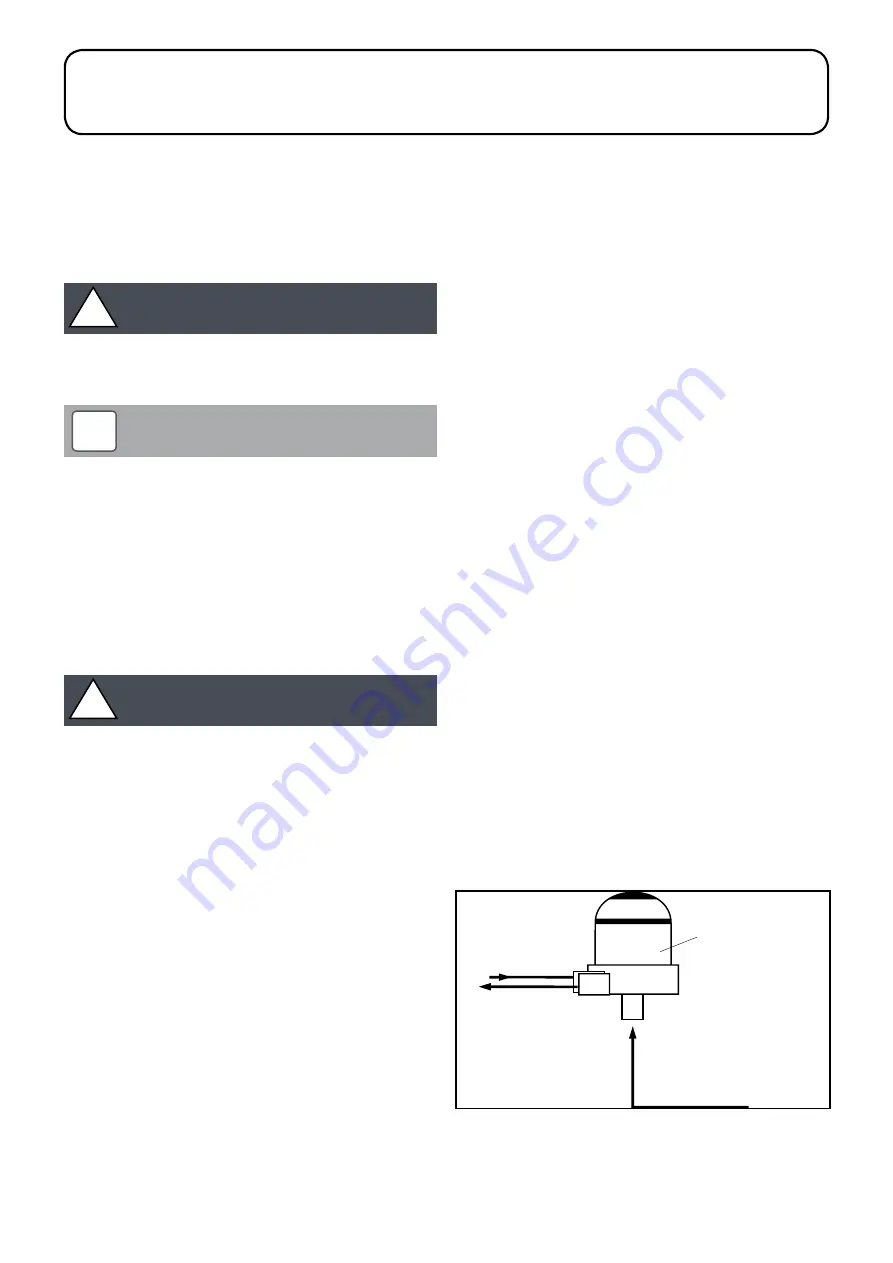
Tiger Loop system - (refer to Figure 3-1 and 3-4)
When The storage tank outlet is below the burner, an alternative to
a two pipe system can be achieved using a 'Tiger Loop' type oil
de-aerator. This effectively removes the air from the oil supply on a
single pipe lift.
The de-aerator is connected close to the boiler as a two pipe
system (omitting the non-return valve) as shown in Figure 3-3.
Refer to the manufacturers instructions supplied with the de-aerator.
The de-aerator must be mounted vertically. See Figure 3-3 and 3-4.
To be used with a de-aerator, the burner must be fitted with an
additional flexible fuel hose - a flexible fuel hose (900 mm) and 3/8"
to 1/4" BSP male adaptor are available to purchase from Grant UK
(product codes: RBS35 and RBS36).
1/4" BSP female
connections
Tiger Loop
SUPPL Y
TO PUMP
RETURN
FROM PUMP
SUPPL Y
FROM TANK
Figure 3-1:
Tiger loop de-aeration device
Summary of Contents for Aerona3 Series
Page 57: ...Section 13 Flue System and Air Supply Page 57 Figure 13 8 Flue clearances...
Page 77: ...Section 19 Spare Parts Page 77 Figure 19 4 15 21kW baffles Figure 19 5 21 26kW baffles...
Page 84: ...Appendix A Page 84 Appendix A...
Page 85: ...Appendix A Page 85...
Page 86: ...Appendix A Page 86...
Page 87: ...Appendix A Page 87...


