


15
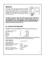
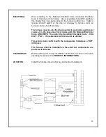
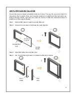
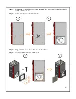
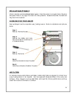
UPFLOW INSTALLATION
The return air opening can be located
on left side or on the right side of the
unit. After installing the filter rack
supplied with the unit we recommend
installing the blower door before
handling the unit.
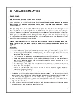
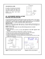
4.0 ACCESSORY INSTALLATION
BLOCKED VENT SWITCH (BVSO)
This gas fired appliance MUST be installed with a blocked vent switch system on the chimney.
A safety switch is included with the furnace to perform this function. It is the installer’s
responsibility to install the switch in accordance with the instructions provided. Not applicable
for Direct Vent systems. Field Controls Model: WMO-1 (Manual Reset)
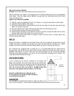
Switch Operation
Blocked vent switches are flue gas safety devices for detecting spillage of flue gases due to a
blocked flue or inadequate draft. After detecting a problem, the switch de-energizes the
system’s burner control.
NEVER reset the switch unless the cause of the blockage has been corrected.
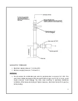
Installation (Figure 1)
1) Drill a 5/8” hole in to the flue vent pipe just upstream of the draft regulator relief
opening.
2) This hole must be before the draft regulator, vertically or horizontally.
3) Remove one of the securing nuts from the threaded tube of the safety switch.
4) Tighten the other securing nut onto the pipe as far as possible.
5) Insert the threaded tube end into the pierced hole of the flue vent pipe.
6) Install the securing nut on the safety switch tube, which protrudes into the flue vent pipe.
Tighten the nut securely.
Figure 1-
Illustration by Granby Industries
Figure 2- BVSO wiring diagram
WARM AIR
AIR
Filter


